


VS-SH10U Set-up and Installation Manual
11
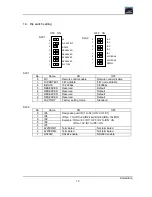
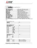
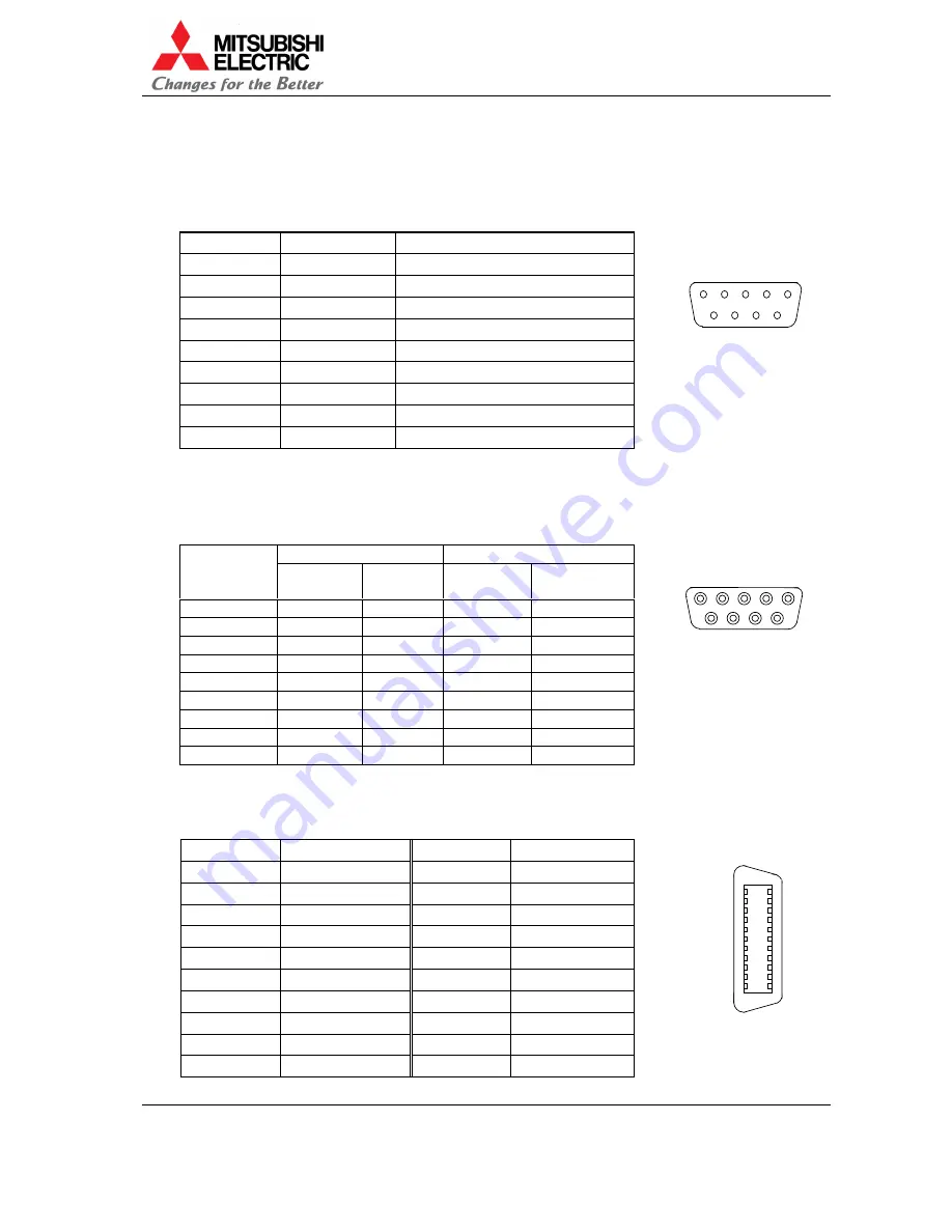
1.3.2. RS-232C
terminal
Terminal: D-sub 9pins (male)
Crossing cable should be used to connect with PC.
Pin assignment:
Pin number
I/O
Signal
1
–
N.C.(No Connection)
2
input
RD (Receive Data)
3
output
SD (Send Data)
4
output
ER (Equipment Ready)
5
–
SG (Signal Ground)
6
input
DR (Data Set Ready)
7
–
N.C.(No Connection)
8
–
N.C.(No Connection)
9
–
N.C.(No Connection)
1.3.3. Control
terminal
Terminal: D-sub 9pins (female)
Straight cable (male – male) should be used to connect.
Pin assignment:
I/O
Signal
Pin number
IN
terminal
OUT
terminal
IN
terminal
OUT
terminal
1
input
output
RXB
TXB
2
input
output
RXA
TXA
3
N.C.
N.C.
4
output
input
TXB
RXB
5
output
input
TXA
RXA
6
N.C.
N.C.
7
N.C.
N.C.
8
GND
GND
9
input
output
RCIN
RCOUT
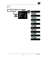
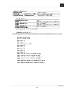
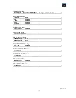
1.3.4. Digital input terminal
Connect to the DIGITAL IN terminal using the DFP cable.
Pin assignment:
Pin number
Signal
Pin number
Signal
1
RXO -
11
RXC -
2
RXO +
12
RXC +
3
RXO Shield
13
RXC Shield
4
RX2 Shield
14
RX1 Shield
5
RX2 -
15
RX1 -
6
RX2 +
16
RX1 +
7
DDCSCL
17
NC
8
DDCSDA
18
SENS
9
NC
19
DDC +5V
10
NC
20
DDC GND
8
9
7
6
5
3
4
1
2
7
6
8
9
1
3
2
5
4
10
1
20
11
MDR20
Summary of Contents for VS-SH10U
Page 1: ...DLPTM Projector VS SH10U Set up and Installation Manual August 30 2002...
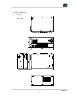
Page 8: ...First edition 8 1 2 Outline drawings 1 2 1 Circuit Box unit mm...
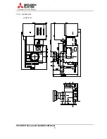
Page 9: ...VS SH10U Set up and Installation Manual 9 1 2 2 Optical Unit unit mm...
Page 56: ...First edition 56 6 2 6 axis adjuster Model Screw holes VS SH10U c e h j...


