


First edition
14
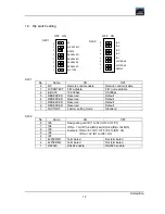
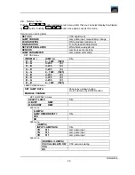
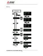
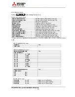
1.6. LED display
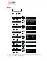
LED display indicates the failure detection result such as shown in the following table.
LED display
Failure detection
0
Fan stop
1
Lamp changer mechanical failure or no workable lamp
2
DMD control circuit failure
3
DMD control circuit failure
4
Lamp changer control circuit failure
5
Internal SRAM failure
6
(not defined)
7
Power failure
n
No error
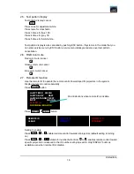
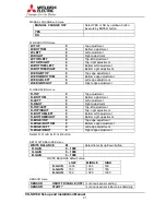
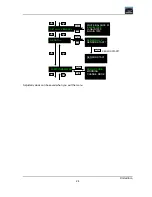
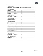
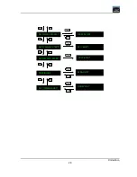
Projector state display
LED display
Projector state
-
(Bar at center)
No signal
.
(Dot)
Stand-by state
.
(Blinking dot)
During shutdown of the projector
1, 2, 3, 4, 5
During startup of the projector
E
While the flash memory is deleted
Displayed While the adjustment memory is updated, etc.
P
While the value is written in the flash memory
Summary of Contents for VS-SH10U
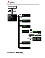
Page 1: ...DLPTM Projector VS SH10U Set up and Installation Manual August 30 2002...
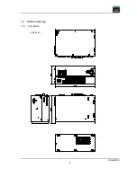
Page 8: ...First edition 8 1 2 Outline drawings 1 2 1 Circuit Box unit mm...
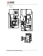
Page 9: ...VS SH10U Set up and Installation Manual 9 1 2 2 Optical Unit unit mm...
Page 56: ...First edition 56 6 2 6 axis adjuster Model Screw holes VS SH10U c e h j...


