First edition
30
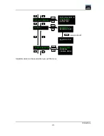
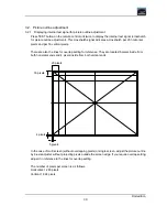
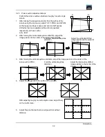
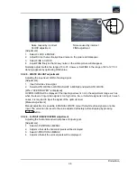
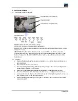
3.2. Picture outline adjustment
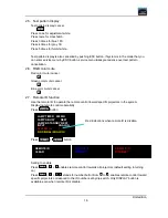
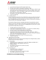
3.2.1. Displaying internal test signal for picture outline adjustment
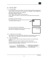
Press TEST button on the remote control unit twice to display the internal test signal (crosshatch
for picture outline adjustment). This crosshatch signal indicates a crosshatch per 20 horizontal
pixels and per 16 vertical pixels.
There are also the lines for overlap setting for reference. They are located 5 pixels inside from
both horizontal ends and 4 pixels inside from both vertical ends.
In the case of multi screen (without overlapping pixels) or single screen, adjust the picture outline
by 6-axis adjuster without projecting pixels outside the screen edge. If you require overlap setting,
adjust it in reference to the lines for overlap setting.
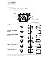
The number of pixels per screen is as follows.
Horizontal: 1,280 pixels
Vertical: 1,024 pixels
20 pixels
16 pixels
4 pixels
5 pixels
Summary of Contents for VS-SH10U
Page 1: ...DLPTM Projector VS SH10U Set up and Installation Manual August 30 2002...
Page 8: ...First edition 8 1 2 Outline drawings 1 2 1 Circuit Box unit mm...
Page 9: ...VS SH10U Set up and Installation Manual 9 1 2 2 Optical Unit unit mm...
Page 56: ...First edition 56 6 2 6 axis adjuster Model Screw holes VS SH10U c e h j...


