First edition
36
c
c
b b
1
4
3
2
a
b
c
b
c
b
b
b
a
a
b
a
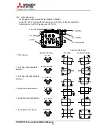
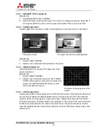
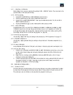
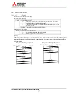
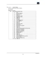
Gradation adjustment point
1
4
3
2
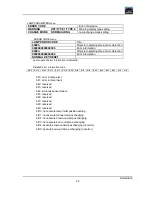
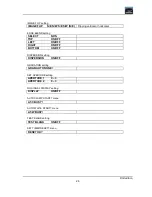
Adjustment item
R/G/B-TOP
R/G/B -BOTTOM
R/G/B -LEFT
R/G/B -RIGHT
A
R/G/B -TOP/LEFT
R/G/B -TOP/RIGHT
R/G/B -BOTTOM/LEFT
R/G/B -BOTTOM/RIGHT
B
R/G/B -EDGE/TOP
R/G/B -EDGE/BOTTOM
R/G/B -EDGE/LEFT
R/G/B -EDGE/RIGHT
C
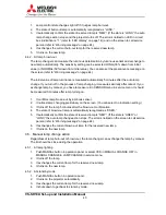
MENU2 adjustment display
(Displayed only when analog is input.)
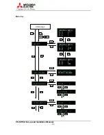
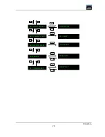
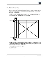
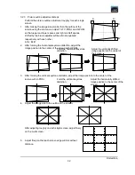
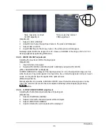
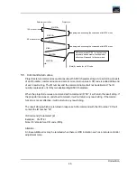
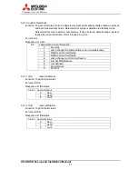
Gradation adjustment procedure
(4-screen multi vision as an example)
1. Adjust to match the luminance/tint level in the edge of
adjacent screens (gray area in the lower left figure)
using adjustment item A and C. In this time, adjust to
align darker part with brighter one with considering
uniformity in a screen.
2. Adjust to match the luminance/tint level in the 4
corners connecting area (area a in the lower right
figure) using adjustment item B.
3. Adjust to match the luminance/tint level in the fringe of
screens (area b and c in the lower right figure) using
adjustment item A and C at first, then compensate it
with B.
4. Repeat the steps from 1) to 3) so as to uniform the luminance/tint level of all colors.
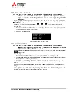
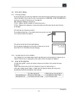
3.5. Video signal adjustment
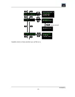
3.5.1. Memory
select
Select the memory number to save adjusted values in. The memory can be selected from 01 to
16 by pressing
MEM LIST
MEM LIST
MEM LIST
MEM LIST
and 01 – 16 in number buttons (See “Video memory select” on page 15).
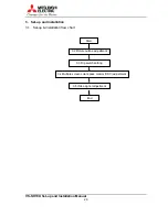
Selected memory number is displayed at the top of MENU1 and MENU 2. If you don’t select the
memory number, the values are saved in MEMORY1. If MENU 1 and MENU2 setting has been
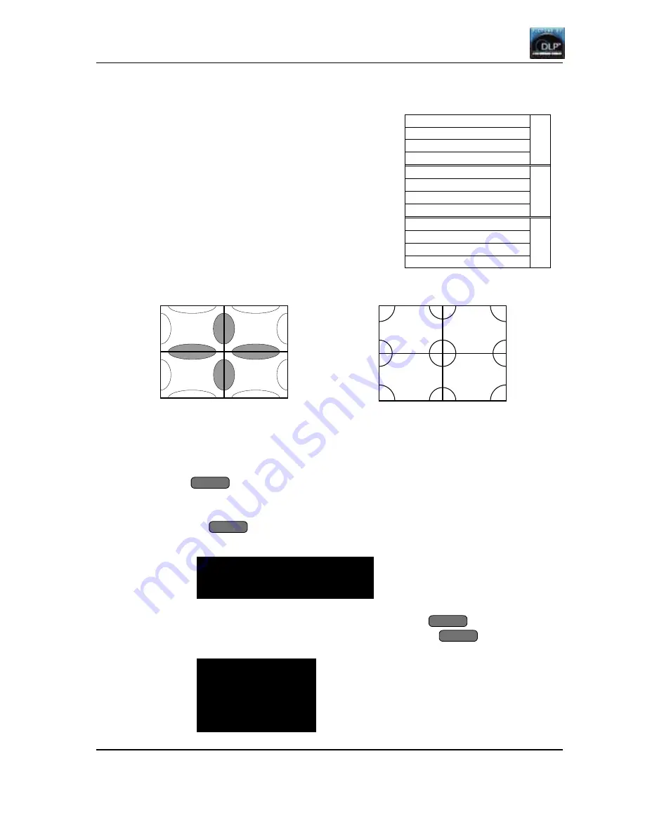
changed, pressing
ESC
ESC
ESC
ESC
button will display OSD (shown below) on which you can choose to
save the data in the selected memory.
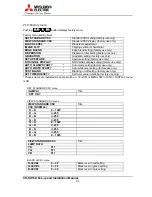
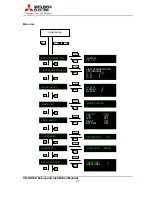
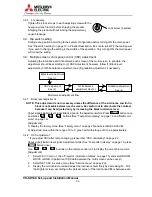
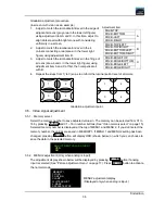
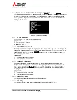
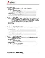
3.5.2. MENU2 adjustment (Only when analog is input)
The adjustment display shown below will be displayed by pressing
M ENU2
M ENU2
M ENU2
M ENU2
button if analog
input is selected (See “Picture adjustment menu” on page 17). Press
ESC
ESC
ESC
ESC
button to activate
the normal mode.
MEMORY 1
CLOCK
POSITION
CLAMP
WHITE ADJUST
V-MASK
SEPARATE SYNC
ADJUSTMENT VALUE SAVED?
YES
NO
Summary of Contents for VS-SH10U
Page 1: ...DLPTM Projector VS SH10U Set up and Installation Manual August 30 2002...
Page 8: ...First edition 8 1 2 Outline drawings 1 2 1 Circuit Box unit mm...
Page 9: ...VS SH10U Set up and Installation Manual 9 1 2 2 Optical Unit unit mm...
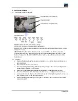
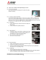
Page 56: ...First edition 56 6 2 6 axis adjuster Model Screw holes VS SH10U c e h j...


