

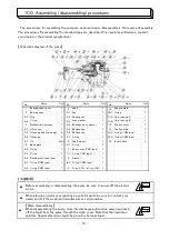
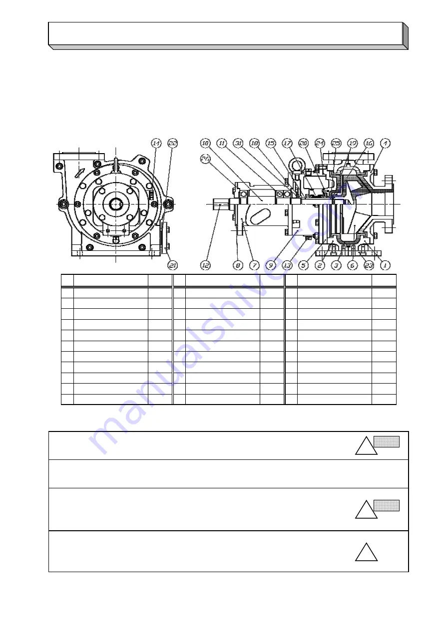
The procedures for assembling the pump are as shown below. Disassembly is the reverse of assembly.
The procedures for assembling the standard type are described. For special specifications, contact
your dealer or the product manufacturer.
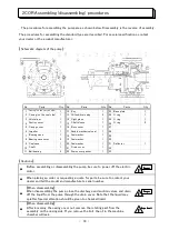
【Schematic diagram of the pump】
No,
No,
No,
1
12
23
2
13
24
3
14
25
4
15
26
5
16
27
6
17
28
7
18
29
8
19
30
9
20
31
10
21
32
11
22
33
【Cautions】
- 14 -
●
【When disassembling】
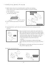
When disassembling the pump, close the discharge and suction valves and drain
off the liquid from the pump through the drain cover. Note that the liquid may
splatter. Special attention should be given to chemical liquid.
●
【When disassembling】
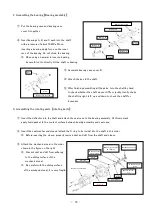
After loosening the casing cover nut, remove the rotating part from the
assembly on the casing side. If you remove the bolt, the oil in the machine
chamber will leak.
●
When placing an order or requesting a quote for parts, be sure to contact your
dealer and tell the model and manufacturer's serial number.
Bearing case cover
Seal case
Shaft
Ball bearing
2
1
3
Suction cover
Casing cover
Impeller
Bearing case
Parts
Casing (on the suction side)
Casing (on the seal side)
Volute liner
1
Q'ty
1
1
1
1
1
1
1
Shaft sleeve
Boss cover
Seal washer
Drain cover
Parts
Key
Oil feed/drain plug
Sight glass
Double mechanical seal
Seal washer
Seal washer
1
Drain cover gasket
1
1
1
1
2
1
Q'ty
1
1
1
O ring
1
1
Parts
Base plate
Q'ty
1
2
●
Before assembling or disassembling the pump, be sure to power off the electric
motor.
O ring
O ring
1
Deflector
1
2COR Assembling (disassembling) procedures
!
!
!
!
Danger
Danger
Danger
Danger
!
!
!
!
Danger
Danger
Danger
Danger
!
!
!
!
Important
Important
Important
Important


