background image

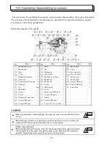
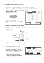
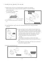
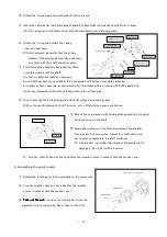
Attach the oil drain plug and sight glass to the seal case.

Insert the seal washer (with liquid gasket applied to both sides) and mechanical seal rotor (large) 

into the casing cover and fasten them with the mechanical seal stationary plate.

Attach the O ring and asseble the casing 

cover and seal case.

※At this moment, be careful that the sliding

    surface of the mechanical seal does not come

in contact with the shaft and other parts.

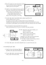
Turn the shaft by hand to check whether there 

is anything wrong with the shaft.

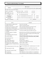
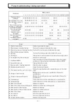
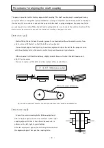
Conduct air tightness tests as necessary.

Air tightness test: Leave the mechanical seal for 10 minutes with a pressure of 0.3 MPa applied to

air at room temperature from the threaded hole of the oil feed plug.

Pour oil through the oil feed plug and attach the oil feed plug and eye bolt.  

※Pour the specified amount of oil. Too much or too little oil may cause early failure. 

Attach the seal washer (with liquid gasket applied to both sides)  

and boss cover to the shaft.

The impeller is of screw type. Secure the shaft and screw

the impeller squarely into the shaft clockwise.

※ The impeller is a rubber lined product. Be careful not to

   damage it. Do no hit it with a hammer.

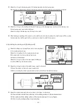
Turn the shaft by hand to check whether the impeller comes in contact with the suction cover.

4、Assembling the pump (pump)

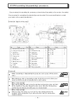
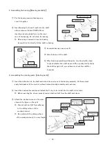
① Attach the rotating part to the assembly on the casing side.

Turn the shaft by hand to check whether the impeller 

comes in contact with the suction cover.

※ 

Take out the nut

Take out the nut

Take out the nut

Take out the nut

 to remove the rotating part from the

  assembly on the casing side. Never take out the bolt.

- 17 -

An air tightness test shows whether the mechanical seal has been assembled properly.

Apply silicon grease to the thread and attach the impeller.

Bos

cover

Im

pell

er

Seal washer

O ring

Mechanical seal

Casing cover

Sight glass

Oil drain plug

Mechanical seal 

Seal washer

Oil feed plug

Eye bolt

Assembly on the casing side

Rotating part

Spring washer

Nut

Summary of Contents for 1CO

Page 1: ...No IM CO201806 C O R type Instruction Manual ...

Page 2: ...on 7 Cautions during non operation 8 Cautions during storage and long non operation 9 Daily checks and maintenance 10 Pump troubleshooting at startup 11 Pump troubleshooting during operation 12 Procedures for aligning the shaft coupling 13 1CO Assembling disassembling procedures 14 2COR Assembling disassembling procedures 14 17 8 4 4 7 10 13 Contents 5 1 2 2 3 9 5 6 ...

Page 3: ...mp with the valves on the discharge and suction pipes fully closed may cause an abnormal rise in the pump liquid temperature resulting in damage to pump components Also avoid pipe blockage Before fitting the belt coupling bolt check the rotation direction of the electric motor For the rotation direction see the pump Before operaing the pump be sure to attach the safety cover Never touch the safety...

Page 4: ...cover removed Shaft seal parts and bearings may become hot If you touch them with your bare hands you may get burned or have an accident Exercise utmost caution when inspecting them Be sure to use a waste oil catch can Do not discharge waste oil directly onto the earth s surface Be sure to comply with applicable laws and regulations with regard to waste disposal Be sure to perform periodical inspe...

Page 5: ...ee the pump Install a valve on each of the discharge and suction pipes for easy inspection and repair Also secure adequate space for inspection and repair Be sure to install an air vent valve on the discharge pipe The suction pipe diameter must be equivalent to or greater than the pump suction opening diameter Make the suction pipe as short as possible and mimimize the number of bends Perform pipi...

Page 6: ...arge and suction pipes fully closed may cause an abnormal rise in the pump liquid temperature resulting in damage to the pump components Also avoid pipe blockage Do not idle the pump Do not idle the pump Do not idle the pump Do not idle the pump Operation without water or liquid in the pump may damage the mechanical seals or other pump components Keep foreign objects from entering the pump Keep fo...

Page 7: ... that liquid may splatter Stop the pump immediately after the discharge valve is fully closed If the pump is likely to freeze in winter remove liquid in the casing Back or negative pressure must not be created in the pump djuring non operation If back or negative pressure is likely to be created fully close the discharge and suction valves If liquid is likely to coagulate during non operation pass...

Page 8: ...s Check the coupling rubber for wear If anything is wrong with the rubber adjust or replace it Direct driven type Every week Pump electric motor check the drive Check the belt for looseness and wear If anything is wrong with the belt adjust or replace it Every month 1250 cc Retighten bolts and nuts When a bearing makes abnormal or high pitched noise it needs to be replaced Overhaul the pump once a...

Page 9: ...ion is generated The motor is overloaded Change the suction position to prevent air from being sucked Improve the suction pipe Check the water level liquid temperature and suction piping resistance in the suction tank and maintain sufficient NPSH Problem Carry out correct wirng Overhaul the discharge pipe and eliminate the cause Blocked pump including freezing Remedies Faulty wiring in the electri...

Page 10: ...ension Improve the suction pipe Check the water level liquuid temperature and suction piping resistance in the suction tank and maintain sufficient NPSH Tighten the bolts and nuts Blocked pump including freezing Abnormal noise is generated Contact your dealer for repair Problems The discharge rate is low The discharge pressure is low Causes Electric motor failure Overhaul the pump and eliminate th...

Page 11: ...se a straight edge or leveling string to avoid misalignment Adjust the belt to the proper tension with the adjusting bolt on the electric motor Avoid overtension and undertension After a new belt is fitted the belt may slightly stretch Be sure to check the belt tension and adjust it as necessary Be sure to replace all the belts at a time instead of the worn belt only For the proper belt tension co...

Page 12: ... be sure to power off the electric motor When placing an order or requesting a quote for parts be sure to contact your dealer and tell the model and manufacturer s serial number O ring COM type 1 R ring COR M ring COM 1 O ring COM type 1 O ring COM type 1 Double mechanical seal 1 Impeller 1 O ring 1 O ring COR type 1 O ring 1 Boss cover COR type 1 Back plate 1 O ring 2 Oil 600cc Shaft sleeve 1 Inn...

Page 13: ...late COM type Fit the Suction plate into the suction cover Fasten with bolts 4pcs Attach the suction cover to the outer casing B with bolts 8pcs 2 Assembling the bearing Bearing assembly Insert bearings A and B each into the shaft with a pressure of about 10 MPa When inserting a bearing apply force on the inner race of the bearing Do not strain the bearing When using a hammer to insert a bearing ベ...

Page 14: ... case fit the back plate into the mechanical seal case and fasten with bolts 3pcs Attach the O ring to inside of the back plate COM type insert the R M ring into the back plate Attach the O ring to inside of the shaft sleeve insert to the shaft Insert the sleeve as thin part comes impeller side Before inserting the sleeve properly remove dust and dirt from the shaft and sleeve Attach the mechanica...

Page 15: ...r oil through the oil supply plug and attach the oil supply plug Pour the specified amount of oil Too much or too little oil may cause early failure COR Attach the O ring to inside of the Boss cover and fit on the impeller Attach the impeller to the shaft COM Attach the O ring to inside of Impeller Attach the impeller to the shaft The impeller is of screw type Secure the shaft and screw the impell...

Page 16: ...om the assembly on the casing side If you remove the bolt the oil in the machine chamber will leak When placing an order or requesting a quote for parts be sure to contact your dealer and tell the model and manufacturer s serial number Bearing case cover Seal case Shaft Ball bearing 2 1 3 Suction cover Casing cover Impeller Bearing case Parts Casing on the suction side Casing on the seal side Volu...

Page 17: ... on the left below so that it protrudes about 3 mm above the base plate and temporarily fasten the casing and base plate with the hexagon socket head cap screws Hammer the knock pin again so that it does not protrude from the base plate Then firmly tighten the screws Use a copper hammer to prevent the knock pin from deforming Pay attention to the orientation so that the internal thread comes to th...

Page 18: ...the deflector into the shaft and attach the seal case to the bearing assembly At this moment apply liquid gasket to the contact surface between bearing assembly and seal case Insert the seal washer and sleeve attach the O ring to its inside into the shaft in this order Before inserting the sleeve properly remove dust and dirt from the shaft and sleeve Attach the mechanical seal in the order shown ...

Page 19: ...e Attach the seal washer with liquid gasket applied to both sides and boss cover to the shaft The impeller is of screw type Secure the shaft and screw the impeller squarely into the shaft clockwise The impeller is a rubber lined product Be careful not to damage it Do no hit it with a hammer Turn the shaft by hand to check whether the impeller comes in contact with the suction cover 4 Assembling th...

Page 20: ...itsuwapump jp http www mitsuwapump jp http www mitsuwapump jp http www mitsuwapump jp Head office Zip code 511 0251 3617 Shinkurahara Ooaza yamada Toincho Inabegun Mie Japan TEL 81 594 76 1100 FAX 81 594 76 1101 ...

Reviews: