background image

Page Number - 3

Form 824845

Important Precautions

•  Always read carefully and understand instruc-

tions prior to using this equipment

•  Brake fluid is highly corrosive.  Wear gloves and 

approved safety goggles at all times, and pre-

vent contact of the fluid with painted surfaces.

•  Consult and follow the vehicle manufacturer’s 

recommended procedures when servicing any 

hydraulic system.

•  Do not use this unit with flammable liquids or 

with fluids at temperatures above 175° Fahren-

heit (80° Celsius).

•  Properly dispose of old fluids, and replenish hy-

draulic systems with new brake fluid from freshly 

opened containers.

•  Do not attempt to pressurize the bleeder/evacu-

ator.  It is designed for vacuum use only.

•  This unit is equipped with an automatic shut-off 

device that will prevent fluid from entering the 

compressed air stream and ejecting through the 

exhaust.  However, if the unit is continuously op-

erated when the reservoir is full, residual pres-

sure will allow the reservoir to completely fill with 

fluid, creating the potential for spillage when the 

lid is removed.  To prevent this situation, empty 

or turn the unit off prior to filling the reservoir 

completely full. 

•  The screws included in Base Kit 822701 are 

provided to secure the base to a work surface.  

Do not use the screws to attach the base to the 

reservoir.

Principal of Operation

This unit is designed for use as a vacuum brake or 

clutch bleeder, or fluid evacuator.  It utilizes com-

pressed air between 60 psi (4.1 bar)and 150 psi 

(10.3 bar), and a venturi system, to build vacuum 

in the reservoir.  By attaching the proper accessory 

to the coupler located on the top of the unit, the 

vacuum can be used to drain brake fluid from a hy-

draulic system such as the brake or clutch systems 

on an automobile.  It can also be used to evacu-

ate a variety of fluids from reservoirs including the 

master cylinder or those for power steering fluid or 

engine coolant.

An automatic master cylinder refill kit is included 

with this unit.  It is conveniently designed for use 

with a standard bottle of brake fluid, to maintain an 

adequate fluid level in the master cylinder while the 

hydraulic system is bled.  Instructions are included 

with the kit for its use.

Instructions for Bleeding Brakes

IMPORTANT: 

This unit is designed for servicing a 

variety of vehicles in a safe, convenient manner.  

However, options such as load sensors or anti-

lock brakes, available on many automobiles, may 

require additional steps or equipment to perform a 

proper service job.  The procedures below are to 

serve as guidelines for the use of this equipment, 

in addition to these guidelines, always follow the 

manufacturer’s recommended procedures when 

servicing each unique vehicle.

Removing old fluid from the brake mas-

ter cylinder

1. Properly park the vehicle on level ground and 

turn the engine off.

2. Clean the exterior of the master cylinder and 

master cylinder cap to prevent dirt from entering 

the master cylinder when the cap is removed.

3. Remove the cap from the master cylinder reser-

voir.

4. Connect clean, regulated (60 psi (4.1 bar) to 150 

psi (10.3 bar)) compressed air to the male quick 

disconnect nipple attached to the swivel air 

inlet, located on one end of the vacuum bleeder 

handle.

5. Connect the appropriate end of the evac tube 

assembly  to the female quick disconnect cou-

pler located on top of the vacuum bleeder.

6. Insert the other end of the evac tube assembly 

into the master cylinder fluid reservoir, and push 

the vacuum bleeder throttle forward to start the 

vacuum (allow a few seconds for vacuum to 

build in the bleeder reservoir before suction oc-

curs).  While evacuating the old fluid, stir it up to 

break loose and remove any sludge that has ac-

cumulated on the bottom and walls of the master 

cylinder.

7. Once all fluid is removed, turn off the bleeder 

and refill the master cylinder with new manufac-

turer’s recommended brake fluid.

Summary of Contents for MV6830

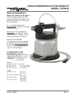
Page 1: ...bar 49 5 oz min 1460 ml min 90 psi 6 2 bar 70 5 oz min 2095 ml min 150 psi 10 3 bar 70 5 oz min 2095 ml min Page Section MV26 1C Form 824845 OCT 2010 VACUUM BRAKE BLEEDER MODEL MV6830 USER S MANUAL Ha...

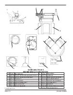
Page 2: ...KE BLEEDING ADAPTER 8 822705 O RING KIT 2 822694 BLEEDING TUBE KIT 9 822706 RESERVOIR GASKET KIT 3 822700 VALVE KIT 10 822709 MUFFLER KIT 4 822701 BASE KIT 11 822722 SUCTION TUBE KIT 5 822702 COUPLER...

Page 3: ...the master cylinder or those for power steering fluid or engine coolant An automatic master cylinder refill kit is included with this unit It is conveniently designed for use with a standard bottle of...

Page 4: ...eed screw air will also be sucked into the bleed tube from around the bleed screw threads This can give the misconception that air is bleeding from the lines however it is normal and does not indicate...

Page 5: ...essed air to the male quick disconnect nipple attached to the swivel air inlet located on one end of the vacuum bleeder handle 4 Connect the appropriate end of the bleed tube assembly to the female qu...

Page 6: ...uthorized field personnel THIS WARRANTY IS EXCLUSIVE AND IS IN LIEU OF ANY OTHER WARRANTIES EXPRESS OR IMPLIED INCLUDING BUT NOT LIMITED TO THE WARRANTY OF MERCHANTIBILITY OR WAR RANTY OF FITNESS FOR...

Page 7: ...ro vert au 1 800 992 9898 Caract ristiques Techniques Capacit du R servoir 1 8 litres 1 9 quarts Longueur du Tuyau de Purge 1 830 cm 72 pouces Longueur du Tuyau d Evacuation 1 220 cm 48 pouces Pressi...

Page 8: ...S DE PURGE 8 822705 KIT JOINT TORIQUE 2 822694 TUYAU DE PURGE 9 822706 KIT JOINT STATIQUE DE RESERVOIR 3 822700 KIT VALVE 10 822709 KIT D ECHAPPEMENT 4 822701 KIT BASE 11 822722 TUYAU D EVACUATION 5 8...

Page 9: ...rvoir y compris le ma tre cylindre ou le fluide de servo direction ou le liquide de refroidissement Cet quipement comprend un kit de remplissage automa tique du ma tre cylindre Il a t con u pour accom...

Page 10: ...is de purge de l air sera aussi aspir dans le tuyau de purge autour du filet de la vis de purge Cela peut donner la fausse impression que de l air fuit des conduites Ceci est normal et n indique pas u...

Page 11: ...air comprim propre et r gularis entre 4 1 bars 60 psi et 10 3 bars 150 psi au mamelon male d connexion rapide attach au joint articul d admission d air situ pr s de la poign e de l appareil de purge...

Page 12: ...ET TENANT POUR TOUTES AUTRES GARANTIES EXPRESSES OU TACITES Y COMPRIS MAIS NON LIMITE A LA GARANTIE DE QUALIT MARCHANDE OU LA GARANTIE D APTITUDE POUR UNE RAISON PARTICULIERE Lincoln n est en aucun c...

Page 13: ...bedarf zu bestellen wenden Sie sich online an uns unter www mityvacparts com oder rufen Sie uns geb hrenfrei an unter Nr 1 800 992 9898 TECHNISCHE DATEN Beh lterkapazit t 1 9 Quarts 1 8 l Entl ftungs...

Page 14: ...8 822705 O RINGSATZ 2 822694 ENTL FTUNGSSCHLAUCHEINHEIT 9 822706 BEH LTERDICHTUNGSSATZ 3 822700 VENTILSATZ 10 822709 SCHALLD MPFERSATZ 4 822701 UNTERTEILSATZ 11 822722 ABSAUGSCHLAUCHEINHEIT 5 822702 A...

Page 15: ...ten oder als Motork hlmittel benutzt werden Ein automatischer Hauptzylinder Auff llsatz wird mit dieser Einheit mitgeliefert Er ist praktischerweise so ge formt dass er mit der Standardflasche f r Bre...

Page 16: ...en Gewinden der Schraube auch Luft in den Entl ftungsschlauch gesaugt Dies kann zu dem Trugschluss f hren dass Luft aus den Leitungen entweiche Dies ist jedoch ein normaler Vorgang und nicht das Anzei...

Page 17: ...s anschlie en Dieser befindet sich am Handgriffende des Vakuumentl ftungsger tes 4 Das zutreffende Ende des Entl ftungsschlauchs mit dem weiblichen Schnellanschluss verbinden der sich oben am Entl ftu...

Page 18: ...artet wurden DIESE GARANTIE IST EXKLUSIV UND STEHT AN STELLE ALLER ANDEREN GARANTIEN AUS GESPROCHENER SOWIE AUCH STILLSCHWEIGEND ANGENOMMENER EINSCHLIESSLICH ABER NICHT BESCHR NKT AUF DIE GARANTIE DER...

Page 19: ...s tenos en l nea en www mityvac com o llame gratuitamente al 1 800 992 9898 ESPECIFICACIONES Capacidad del dep sito 1 9 cuartos de gal n 1 8 litros Longitud del tubo de purga 72 pulg 1 830 cm Longitud...

Page 20: ...EGO DE JUNTA T RICA 2 822694 CONJ DE TUBO DE PURGA 9 822706 JUEGO DE EMPAQUETADURA DEL DEP SITO 3 822700 JUEGO DE V LVULA 10 822709 JUEGO DE SILENCIADOR 4 822701 JUEGO DE BASE 11 822722 CONJ DE TUBO D...

Page 21: ...cluye un juego de relleno autom tico de cilindro maestro con esta unidad Est dise ado conveniente mente para usar con un cilindro est ndar de fluido de freno para mantener un nivel adecuado de fluido...

Page 22: ...s tuber as Sin embargo esto es normal y no indica un funcionamiento defectuoso Para impedir o reducir la entrada de aire recubra las roscas del tornillo de purga con grasa de silicona antes de la purg...

Page 23: ...tubo de purga al acoplamiento hembra de desconexi n r pida ubicado en la parte de arriba del purgador de vac o Nota Consulte en las gu as de fabricante del veh culo el procedimiento de purga de vac o...

Page 24: ...ANT A ES EXCLUSIVA Y REEMPLAZA CUALQUIER OTRA GARANT A EXPL CITA O IMPL CITA INCLUIDA LA GARANT A DE COMERCIALIZACI N O GARANT A DE IDONEDAD PARA UNA CIERTA FINALIDAD PERO SIN LIMITARSE A LAS MISMAS E...

Reviews: