Document No.: E20-018-00
7
5.2.
Installing EJ-210
5.2.1.
Top of Control Box
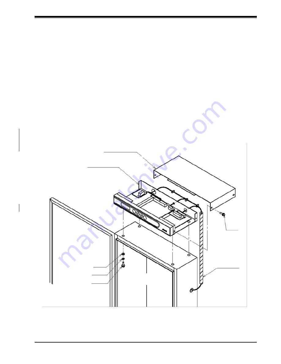
Use the four M6 screws supplied to mount the EJ-210 on top of the control box.
(1) Drill mounting holes in the position where the EJ-210 is mounted.
Mounting dimensions: 115 mm × 350 mm (Refer to the overall view drawings.)
Mounting screws:
M6 × 4 (supplied)
(2) Open the top cover of the EJ-210.
(3) Use the M6 screws supplied to secure the EJ-210.
NOTE 1: Use only the screws supplied. If other screws are used, they may contact and
damage the circuit board.
NOTE 2: Do not remove the rubber feet from the EJ-210. Removing the rubber feet may
result in damage to the circuit board when the EJ-210 is installed.
(4) When wiring is complete, close the top cover.
Figure 5-1: Example of installation on top of the control box
Control box
M6
Boiler operation terminal EJ-210
top cover
Boiler operation terminal EJ-210
main unit
Machine
screw
Heat-resistant
tube
Front panel
Plain washer
Spring washer
M6 screw


