Document No.: E20-018-00
11
6.3.
Terminal Arrangement on Control Circuit Board
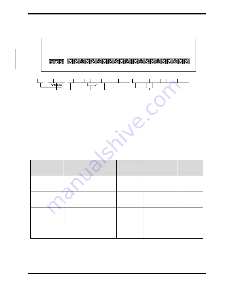
Terminal arrangement on the I/O board is as shown below.
Figure 6-2: Terminal arrangement on EJ-210 I/O board
6.4.
Wires for Use
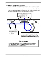
Use wire appropriate for the application that does not exceed the maximum length.
Table 6-1: List of wires
Location used
Standard
Cross-
sectional area
[mm
2
]
Maximum length
[m]
Remarks
Signal wire
High heat-resistant wire
Example: CV wire
(*)
, HIV
wire
(*)
+ heat-resistant tube
1.25 or larger
5
Procured on-
site
RS-422
communication
line wire
Twisted pair cable
FCPEV
(*)
, φ0.9 mm, 2P,
Copper braided screen
―
2
(Boiler to
equipment)
Procured on
site
M-NET3
communication
line wire
Shielded LAN cable
CAT 5 or above, single-wire
STP straight cable
―
100
(HUB to
equipment)
Procured on-
site
Steam pressure
sensor wire
AWM2840
(*)
(3-core shielded
cable)
―
2
Supplied as
optional
extra
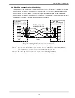
NOTE 1: The RS-422 communication line wire is required for a boiler with BL-model or XJ1-model
controller mounted.
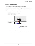
NOTE 2: The steam pressure sensor wire is required to install the optional steam pressure sensor.
EJ21 I/O board
66
5
45
85
22
13
6
79
19
36
76
P-
P1
P+
J4
J3
J2
J1
89
88
6
79 19 76 36
13 22 85 45
5
66
P+ P1 P-
J3 J2 J1 88 89
J4
FG
N(S)
G(FG)
G(FG)
N(S) G(FG)
L(R)
L(R)
G(FG)
Po
wer
su
p
p
ly
(L
p
h
as
e
)
Fra
m
e
g
ro
un
d
(F
G
)
Po
wer
su
p
p
ly
(N
p
ha
se
)
Si
g
n
a
l o
u
tp
u
t
(b
o
ile
r o
pe
ra
tio
n
)
Si
g
n
a
l o
u
tp
u
t
(e
m
e
rg
e
n
cy
s
to
p
)
Si
g
n
a
l o
u
tp
u
t
(h
ig
h
fi
re
in
stru
cti
o
n)
Si
g
n
a
l o
u
tp
u
t
(c
om
bu
sti
on
in
stru
cti
on)
Si
g
n
a
l i
np
u
t
(o
p
e
ra
tio
n
)
(L
p
h
as
e
)
Ste
a
m
p
re
ss
u
re
se
ns
o
r (o
p
tio
n
a
l)
Sig
na
l i
npu
t (o
pe
ra
tion
)
(N
p
h
a
se
)
Si
g
n
a
l
in
p
u
t
(b
oi
le
r
fa
il)
Si
g
n
a
l i
np
u
t
(s
ta
rt)
Si
g
n
a
l i
np
u
t
(h
ig
h f
ire
)
Si
g
n
a
l i
np
u
t
(c
om
b
us
tio
n
)
Box terminals
Gray
Red


