Document No.: E20-018-00
12
6.5.
Signal Wires
6.5.1.
AC Input Signal
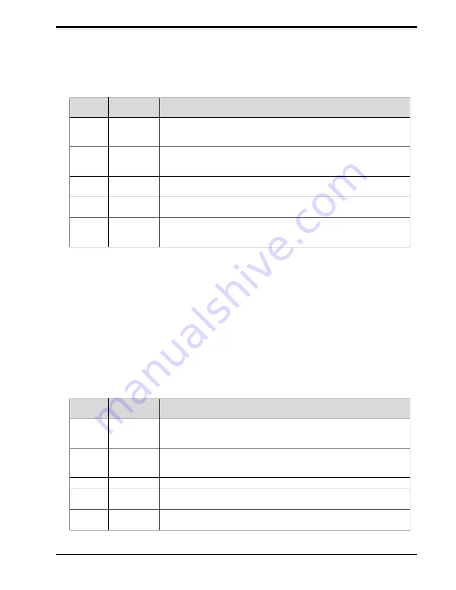
The EJ-210 has the following five AC inputs.
Table 6-2: List of AC input signals
Terminal
number
Signal
name
Connection position on boiler side
5–66
Combustion
signal
Connect to a part that has 120 VAC applied while the solenoid valve
is open, in synchronization with the operation of the solenoid valve for
low fire operation.
45–66
High fire
signal
Connect to a part that has 120 VAC applied while the solenoid valve
is open, in synchronization with the operation of the solenoid valve for
high fire operation.
85–6
Start signal
Connect to a part that has 120 VAC applied during startup of boiler
combustion control.
13–6
Operation
signal
Connect to a part that has 120 VAC applied while the “OPERATION”
switch is ON.
22–6
Boiler fail
signal
Connect to a part that has 120 VAC applied when the boiler is
stopped due to an alarm judgment. In principle, connect to the buzzer
output.
NOTE 1: The connection positions in the table above assume a general MIURA boiler. The
connection position varies depending on the boiler control type and Sequence. Contact
your dealer or MIURA sales office for details.
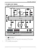
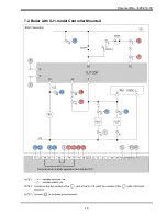
When MIURA standard Sequence are used, refer to “7. EXAMPLES OF WIRING”.
NOTE 2: When the EJ-210 is connected to MIURA boilers without No. 66 terminal, short-circuit
the No. 66 and No. 6 terminals.
6.5.2.
Output Signal
The EJ-210 has the following 5 contact outputs. The No. 19 and No. 79 terminals and No. 36
and No. 76 terminals are required for control. Be sure to make connection with the boiler for
these terminals.
Use the No. J1 and No. J2 terminals and No. J3 and No. J4 terminals if required.
The contact rating is normally-closed contact (b-contact), 250 VAC, 1 A (resistance load).
Table 6-3: List of output signals
Terminal
number
Signal
name
Connection position on boiler side
19–79
Combustion
instruction
This is a contact signal to switch boiler standby and combustion.
Make connection for the No. 19 and No. 79 terminals in series with
the boiler high setting pressure switch wiring.
36–76
High fire
instruction
This is a contact signal to switch boiler combustion and high fire.
Make connection for the No. 36 and No. 76 terminals in series with
the boiler low setting pressure switch wiring.
88–89
Spare
Not used
J3–J4
Emergency
stop
Contacts open when boiler is set to standby during MI control for
safety reasons.
J1–J2
Boiler
operation
During automatic operation under MI control, contacts close when
boiler is operating or open when boiler is not operating.


