MFP250 / 400 / 800
Initial Start Up
76609594EN-MFP-NH-V2.0.docx 24/40
4.1.4
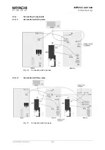
Connecting Secondary Cable
Fig. 12: Secondary cable connection on
weld head (typical)
Fig. 13: Secondary cable connection
on weld pincers (typical)
Connect the secondary cables with the corresponding connections on weld
head/weld pincers and welding current control or welding transformer.
For the polarity of the connections please check the manual of the welding current
control.
Depending on the used material a reversed connection of the poles could be
advantageous.
Please ensure the following to maintain as low a current resistance in the secondary
circuit as possible:
The cable lugs should make contact with the mounted component over as great a
surface area as possible.
Secondary cables should be laid as closely as possible and bound with cable ties to
maintain a limited secondary window.
Secondary cables should not be contacted to other parts conducting current and
should not form shunt circuit.
Contact surfaces should be clean.
Contact surfaces should not be corroded.
Screw connections should not loosen during operation..
Caution
When welding materials which are widely disparate in the electrical voltage sequence an
additionally voltage occurs by the Peltier effect. This voltage is added to the voltage of
the welding current control (recommended) or acts against it, depending on the
secondary cable pole configuration. A secondary cable pole configuration which suits
your particular application should therefore always be selected.
The attachment of a second (third) secondary cable to each pole increases the cable
cross section, thus reducing the current resistance. The shorter the secondary cable, the
lower the conducting loss.

