

MFP250 / 400 / 800
Content
76609594EN-MFP-NH-V2.0.docx 3/40
Content
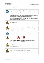
1
General Information ............................................................................................. 5
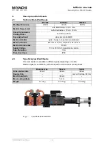
2
Description Weld Heads ...................................................................................... 6
2.1
Technical Data Weld Heads .............................................................................................. 6
2.2
Type Overview Weld Heads .............................................................................................. 6
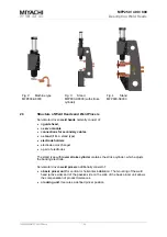
2.3
Structure of Weld Heads and Weld Pincers .................................................................... 7
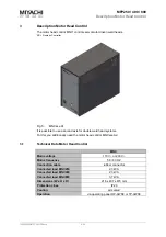
3
Description Motor Head Control ........................................................................ 8
3.1
Technical Data Motor Head Control ................................................................................. 8
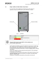
3.2
Design and Mode of Action Motor Head Control ............................................................ 9
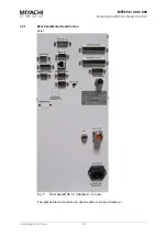
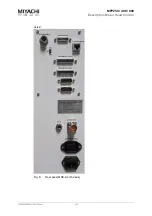
3.2.1
Rear Panel Motor Head Control .................................................................................................... 10
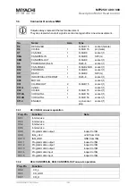
3.3
Connector Overview MNC ............................................................................................... 12
3.3.1
X6: I/O-ISQ one-axis operation ..................................................................................................... 12
3.3.2
X8A: CANOPEN-IN, X8B: CANOPEN-OUT one-axis operation ................................................... 12
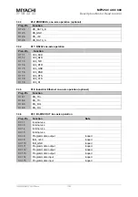
3.3.3
X12: PROFIBUS, one-axis operation (optional) ........................................................................... 13
3.3.4
X17: RS232 one-axis operation ..................................................................................................... 13
3.3.5
X18: Industrial Ethernet one-axis operation (optional) ............................................................... 13
3.3.6
X31: I/O-MNC OUT two-axis operation ......................................................................................... 13
3.3.7
X112A, X112B, X113A, X113B: Programmable Plugs ................................................................. 14
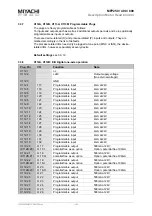
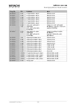
3.3.8
X112A, X112B: E/A Digital one-axis operation ............................................................................ 14
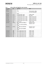
3.3.9
X113A, X113B: E/A Digital two-axis operation ............................................................................ 16
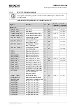
3.3.10
X112, X113: Default Assignment .................................................................................................. 17
3.3.11
X114: ENABLE ................................................................................................................................ 20
3.3.12
Plugs Motor Heads and Pincers ................................................................................................... 20
4
Initial Start Up .................................................................................................... 21
4.1
Electrical Connections .................................................................................................... 21
4.1.1
Mains Connection .......................................................................................................................... 21
4.1.2
Connecting Components .............................................................................................................. 22
4.1.3
Connecting Safety Circuit (ENABLE) ........................................................................................... 23
4.1.4
Connecting Secondary Cable ....................................................................................................... 24
4.1.5
Connecting Voltage Measurement ............................................................................................... 25
4.1.6
Connecting Locking Cylinder (Pincers only) ............................................................................... 26
4.1.7
Connecting Stroke Cylinder .......................................................................................................... 26
4.1.8
Connecting Proximity Switches ................................................................................................... 27
4.2
Mounting Scheme ............................................................................................................ 30
4.3
Initial Commissioning ...................................................................................................... 31
4.4
Setup ................................................................................................................................. 31
4.4.1
Setting the Electrodes ................................................................................................................... 31
4.4.2
Setting the Welding Force ............................................................................................................. 31
4.5
Integration in Automated Installations .......................................................................... 31
4.5.1
Connection to Field Bus Systems ................................................................................................ 31


