MFP250 / 400 / 800
Indexes
76609594EN-MFP-NH-V2.0.docx 39/40
7
Indexes
7.1
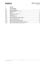
Table of Figures
Fig. 1:
Pincers MFP400-Z700H ......................................................................................................................................... 6
Fig. 2:
Machine type MFP800-A9000 ................................................................................................................................ 7
Fig. 3:
Stand MFP800-H9000 (with stroke cylinder) .......................................................................................................... 7
Fig. 4:
Stand MFP800-S9000 ............................................................................................................................................ 7
Fig. 5:
MNCxxx-A1……. ..................................................................................................................................................... 8
Fig. 6:
Front MNC………. ................................................................................................................................................... 9
Fig. 7:
Rear panel MNC-A1 (Standard – 1st axis) ........................................................................................................... 10
Fig. 8:
Rear panel MNC-A2 (2nd axis) ............................................................................................................................. 11
Fig. 9:
Plugs X9 and X10 ................................................................................................................................................. 20
Fig. 9:
Connection with one axis ...................................................................................................................................... 22
Fig. 10:
Connection with two axes ..................................................................................................................................... 22
Fig. 11:
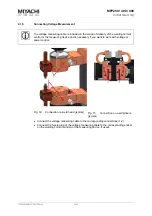
Secondary cable connection on weld head (typical) ............................................................................................. 24
Fig. 12:
Secondary cable connection on weld pincers (typical) ......................................................................................... 24
Fig. 13:
Connection on weld head (typical) ........................................................................................................................ 25
Fig. 14:
Connection on weld pincers (typical) .................................................................................................................... 25
Fig. 15:
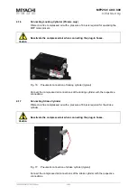
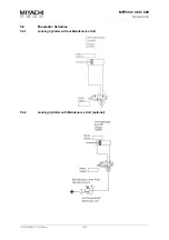
Pneumatic connection of locking cylinder (typical) ............................................................................................... 26
Fig. 16:
Pneumatic connection of stroke cylinder (typical) ................................................................................................. 26
Fig. 17:
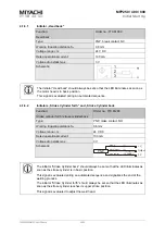
Proximity switch (typical) (below the cover cap of the weld head) ........................................................................ 27
Fig. 18:
Proximity switch (typical) (below the cover cap in the stroke cylinder) ................................................................. 27
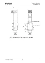
Fig. 19:
Mounting scheme MFPxxx machine type (for automation) ................................................................................... 30

