

MFP250 / 400 / 800
Description Motor Head Control
76609594EN-MFP-NH-V2.0.docx 9/40
3.2
Design and Mode of Action Motor Head Control
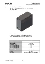
The motor head control is equipped with measuring and control electronics.
Operation is carried out with the operating panel OP-AWS3 / TP-AWS3.
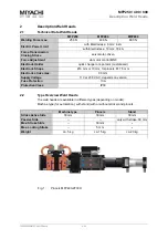
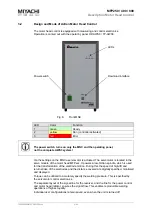
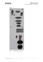
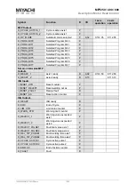
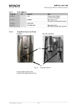
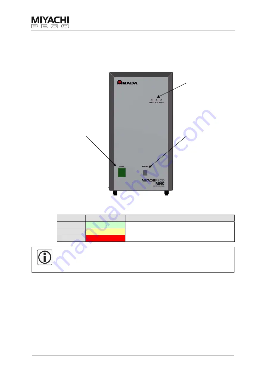
Power switch
Fig. 6:
Front MNC
LEDs
Download interface
LED
Color
Function
1
green
Ready
2
yellow
Run (controller activated)
3
red
Error
The power switch turns on only the MNC and the operating panel,
not the complete AWS3 system!
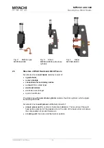
Via the settings on the MNC a servomotor is actuated. The servomotor is located in the
servo module of the motor head MFPxxx. It powers a low-friction spindle, which is used
for the transformation of the electrode motion. During this the speed of high-lift and
return stroke of the electrodes and the distance covered are digitally specified, monitored
and displayed.
Torque can be utilized to accurately specify the welding pressure. This is specified by
the servomotor control electronics..
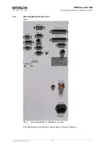
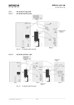
The separate layout of the signal line for the resolver, and the line for the power control
and motor head initiator, ensures the signal flow. This enables reproducible welding
operations of highest quality.
Individual user configurations remain saved, even when the unit is turned off.