CHAPTER 7: MAINTENANCE
MODEL 250DP DUAL PULSE
RESISTANCE WELDING POWER SUPPLY
7-10
990-280
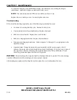
To adjust the trimpots, press [ENTER] to display the calibration screen listing the trimpot
adjustments. Adjust the trimpots as instructed on the screen.
NOTE:
The current measured at TP5 must not drift more than ±1.5?A.
Replace the cover and top screws. Securely tighten all screws.
Troubleshooting
If the circuit breaker trips repeatedly, one of the following is probably the cause:
x
Overload - Exceeding the duty cycle. Reduce the duty cycle.
x
Control printed circuit board malfunction. Replace the board.
x
Defective circuit breaker. Replace the circuit breaker.
x
Defective charging transformer. Replace the transformer.
x
Misconnected charging transformer. Refer to figures 7-2 through 7-5, as appropriate to the
input line voltage.
x
Capacitor bank. Charge the bank with an external 400 volt DC power supply. After 5
minutes, the steady state current should be less than 10 milliamps. If it is not, one or more of
the capacitors is shorted. Discharge the capacitor bank with a 500 to 2000 ohm, 25 watt
resistor to ground and replace the defective capacitor.
WARNING:
Do not discharge the capacitor bank by shorting it directly to ground. The stored energy
could be sufficient to melt the shorting tool in an explosive manner.
After making any repairs and checking the results, replace the cover and tighten all screws.
µA.


