APPENDIX A: TECHNICAL SPECIFICATIONS
MODEL 250DP DUAL PULSE
RESISTANCE WELDING POWER SUPPLY
990-280
A-15
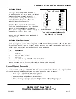
Air Valve Driver 2
The output of the AIR VALVE DRIVER 2
receptacle provides 24 VAC to power a second air
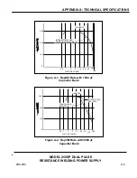
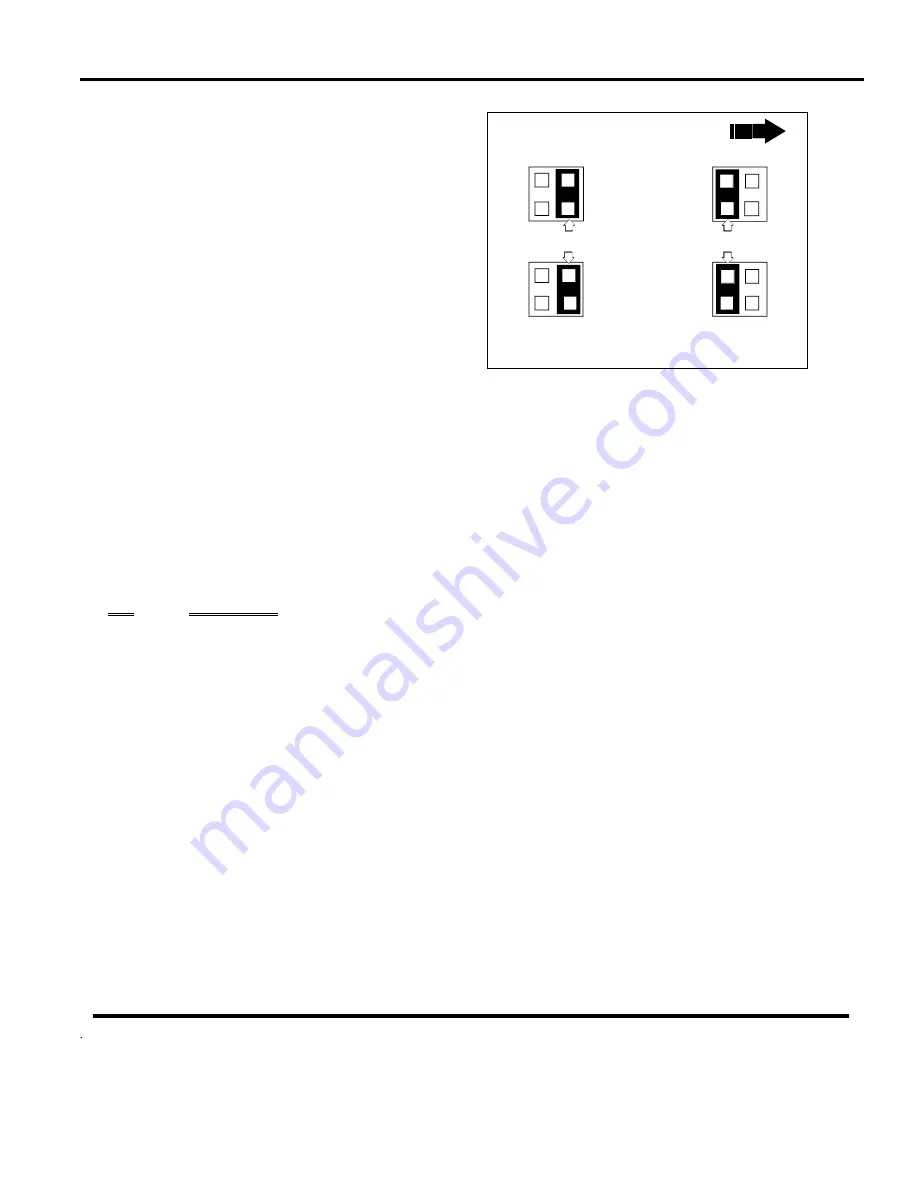
actuated weld head. Jumpers E10 and E11,
located near the lower right hand corner of the
control board must be moved to the correct
positions, as shown in figure A-4.
Air valve driver 2 is wired only for 24 VAC
through receptacle Pins 1 and 2. Pins 3 and 4 are
not provided. To provide power to Air valve
driver 2, move Jumpers E10 and E11 and program
WELD HEAD TYPE to DUAL AIR.
NOTE:
When air valve driver 2 is used, Relay 1
cannot be used.
Air Valve Driver Receptacles
The 4-pin receptacles located on the rear panel are AMP P/N 206430-1 (Unitek Peco PN 550-062). The
mating plug is an AMP 206429-1 (Unitek Peco PN 520-107), which uses a cable clamp, Amp 206358-2
(Unitek Peco PN 245-084). Air Valve Driver 1 is wired as follows:
Pin
Description
1
24
VAC
2
115 and 24 VAC return
3
115
VAC
4
Air head sensing - externally connected to Pin 2
NOTE:
Connect Pin 2 to Pin 4 on a non-Unitek Peco air actuated weld head.
Control Signals Connector
A 15-pin, sub-miniature D-type CONTROL SIGNALS connector, located on the rear panel, is provided for
the two relays and seven single pole inputs. The relays and switch inputs are used to:
x
Remotely select Weld Schedules 1 through 127
x
Remotely inhibit recharging the capacitor bank
x
Invoke an emergency stop condition to abruptly terminate the welding sequence.
E10
E11
E10
E11
Single Air Head
Dual Air Head
Jumpers
Jumpers
Rear of Unit
Figure A-4. Jumper Selection for
Air Valve Driver Control


