APPENDIX A: TECHNICAL SPECIFICATIONS
MODEL 250DP DUAL PULSE
RESISTANCE WELDING POWER SUPPLY
990-280
A-19
Relay Outputs
Two output relays can be used to provide status (timing) signals to external devices. They can also provide
an on (closed) state during a Run state or if there is an alarm.
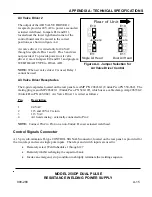
Relay 1 can also be used to control a second 24 VAC air actuated weld head. (Refer to Air Actuated Weld
Head Connections for the appropriate hook-up connections and figure A-3 for appropriate jumper
connections.)
Relay 2 can provide a 5 to 50 VDC signal.
When used to provide status (timing) signals, the relays can be independently programmed as follows:
x
In Basic Mode, each relay can be programmed on (closed) or off (open) during either of the two
weld periods.
x
In Roll Spot Mode, each relay can be programmed on (closed) or off (open) during either of the
two weld periods or during the cool period (between each spot weld cycle).
x
In Repeat Mode, each relay can be programmed on (closed) or off (open) during either of the two
weld periods or during the off period (between each Repeat cycle).
In all of the above cases, if the relay is programmed to be on (closed), it will close at the beginning of the
scheduled period and open at the end of that period. If scheduled to be closed during any successive
periods, it will not open at the end of the first period, but will remain closed during both (or all) periods for
which it is scheduled to be closed.
The 24 to 115 VAC input and output for Relay 1 are Pins 8 and 15, respectively, of the CONTROL
SIGNALS connector. The 5 to 50 VDC input and output for Relay 2 are Pins 6 and 13, respectively. You
must supply the voltage source and, in each case, the ungrounded side of the AC power source for Relay 1.
The DC power source for Relay 2 should be connected to the 250DP as illustrated in figure 3-5 in Chapter
3. Either relay is capable of switching up to 250 ma.
RELAY 1 is
also
used to control Air Valve Driver 2.
The options menu can be used to specify Dual Air Head 2. Under this condition, Relay 1 will display Dual
Air. In the program state, the options for Relay 1 then must be either AIR HEAD 2 or NOT USED. The
second air head will be actuated in any schedule in which Relay 1 is defined as AIR HEAD 2. The standard
valve driver will be actuated in any weld schedule in which Relay 1 is defined as NOT USED.

