IS-120B
4. How to Operate Screens
4-10
(
g
)
STEPPER COUNT
The number of welds at the present step is displayed when the
STEPPER
(
See
(8).(e)
)
on the
MODE SWITCH
screen is turned on.
(
h
)
STEP #
The present number of steps is displayed when the
STEPPER
on the
MODE
SWITCH
screen is turned on.
(
i
)
WELD COUNT
The present number of welds is displayed when the
WELD COUNT
(
See
(8).(b)
)
on the
MODE SWITCH
screen is turned on.
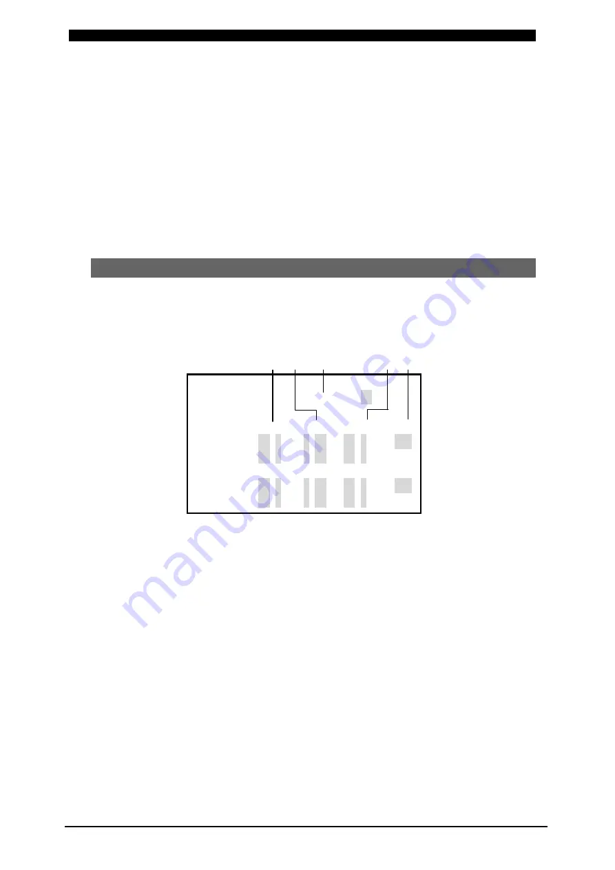
(5) MONITOR SET Screen
Set the conditions such as the welding current from which good or bad weldment is
judged, secondary voltage, etc.
If the monitored welding current, secondary voltage, etc., are out of those conditions,
a trouble signal is output, and it can be used to activate an alarm buzzer, alarm
lamp, and so on.
(b) (c) (a)
(d)
(e)
-MONITOR
SET
SCHEDULE
#01
CURRENT
VOLT
POWER
PULSE
WELD1
HIGH
99.9kA
9.99V
99.9kW
100%
WELD1
LOW
00.0kA
0.00V
00.0kW
WELD2
HIGH
99.9kA
9.99V
99.9kW
100%
WELD2
LOW
00.0kA
0.00V
00.0kW
(
a
)
SCHEDULE #
Input the No. of the
SCHEDULE
to monitor
(
to set the schedules
)
.
(
b
)
CURRENT HIGH/LOW
Set the upper limit
(
HIGH
)
and lower limit
(
LOW
)
of the welding current for
each of
WELD1
and
WELD2
.
(
c
)
VOLT HIGH/LOW
Set the upper limit
(
HIGH
)
and lower limit
(
LOW
)
of the secondary voltage for
each of
WELD1
and
WELD2
.
(
d
)
POWER HIGH/LOW
Set the upper limit
(
HIGH
)
and lower limit
(
LOW
)
of the electric power for each
of
WELD1
and
WELD2
.
(
e
)
PULSE HIGH
If the percentage of the welding current pulse to the pulse width in the full wave
mode exceeds the percentage set in the PULSE HIGH, ERROR signal is
output.


