background image

Hana

®

 Orthopedic Surgery Table Owner’s Manual

Mizuho OSI 2017

32

NW0508 Rev N

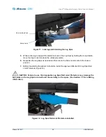
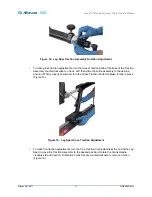
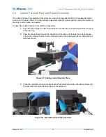
Figure 16:  Leg Spar Fine Traction Adjustment

During initial patient setup, the gross traction should be adjusted for the patient’s height to allow operative 
traction to be applied and released using the Crank Handle for fine traction adjustments.

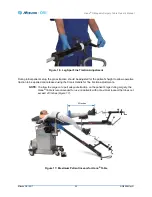
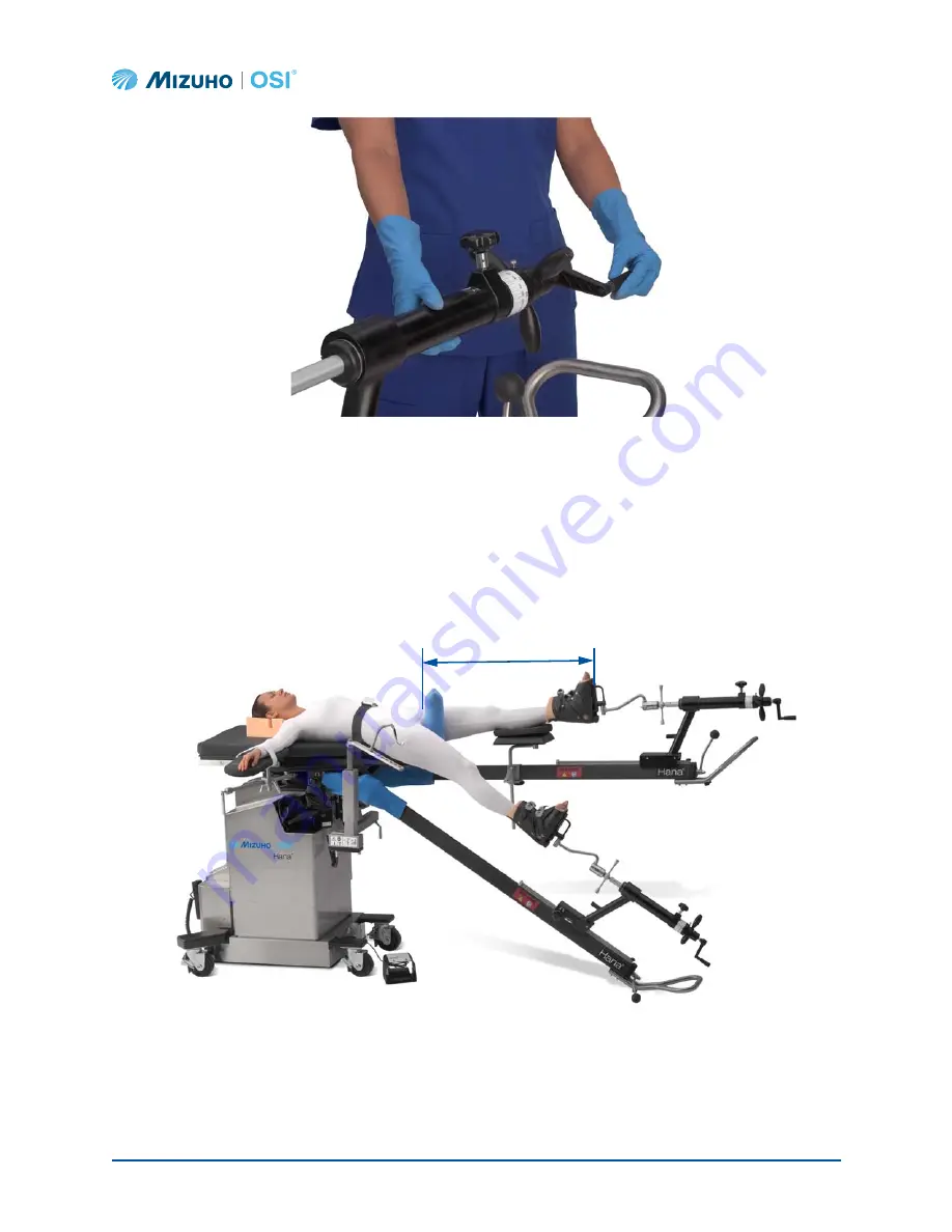
NOTE: To allow the surgeon to pull adequate traction on the patient’s legs during surgery, the 

Hana

®

 Table is recommended for use on patients with a maximum inseam that does not 

exceed 43 inches (Figure 17).

Figure 17:  Maximum Patient Inseam for Hana

®

 Table

43 inches

Summary of Contents for Hana 6875

Page 1: ...0 Fax 1 510 429 8500 WWW MIZUHOSI COM WWW NEWHIPNEWS COM Emergo Europe Molenstraat 15 2513 BH The Hague The Netherlands Hana Orthopedic Surgery Table 6875 6875I 6875J Owner s Manual This manual is available in the following versions English EN Spanish ES French FR German DE Italian IT Portuguese PTBR Japanese JA Chinese ZH Multilingual ML ...

Page 2: ...14 3 2 1 Breaker Power Panel 15 3 2 2 Control Panel 15 3 3 Hana Hand Pendant Control Pad Operation 18 3 4 Emergency Stop Button 20 3 5 Casters 21 3 6 Moving the Table 22 4 Inspection 23 4 1 Acceptance 23 4 2 General Inspection 23 4 3 Pre Procedure Post Procedure 23 4 4 Preventative Maintenance 24 5 Function Check 25 6 Standard Component Installation and Adjustment 27 6 1 Hana Radiolucent Leg Spars...

Page 3: ...etal Traction with Traction Foot Plate Assembly 82 8 3 IM Femoral Nailing Unilateral Skin Traction 86 8 4 IM Femoral Nailing Lateral Decubitus Position with Bilateral Skin Traction 89 8 5 IM Tibial Nailing Supine with Unilateral Skin Traction 92 8 6 Retrograde IM Femoral Nailing Supine with Unilateral Skin Traction 95 8 7 Hip Pinning Supine With Unilateral Skin Traction 99 8 8 Hip Pinning Supine W...

Page 4: ...140 11 3 On Off Circuit Breaker Power Switch 140 11 4 Component Circuit Breakers 141 11 5 Linear Actuators 141 11 6 Battery System 141 12 Troubleshooting 143 13 Technical Drawings and Parts List 146 13 1 Replacement Spare Parts List 146 13 2 Interconnect Diagram 100V 120V 220 230V Models 148 14 Technical Support 149 14 1 Contact for Parts and Service 149 14 2 Order Replacement Parts 149 14 3 Retur...

Page 5: ... are used in this manual and on the equipment Table 1 Symbols and their Meanings Symbol Meaning This symbol indicates an authorized representative in the European Community This symbol indicates this equipment is an applied part TYPE B in accordance with IEC 60601 1 and is generally suitable for applications involving external or internal contact with the patient excluding the heart The patient ci...

Page 6: ...his symbol indicates a potential Pinch Point hazard This symbol indicates the Emergency Stop This symbol indicates the Red Zone Use a Traction Hook Extender as needed to keep the Traction Brake Cover from entering this zone See Section 6 6 for more information This symbol indicates rotation in two directions This symbol indicates rotation in one direction This symbol indicates Alternating Current ...

Page 7: ... to unlock and rotate clockwise to lock This symbol indicates the Foot Pedal for the Femur Lift Assembly This symbol indicates the location of the Emergency Crank Handle for manual operation of the Femur Lift Assembly See Section 6 10 5 for more information This symbol indicates the table weight limit This symbol indicates Small Size This symbol indicates Large Size regular This symbol indicates E...

Page 8: ...on This symbol indicates the proper method for connecting the Femur Lift cable Align the red dots on the receptacle and the plug then insert the plug See Section 6 10 2 for more information This symbol indicates the proper method for disconnecting the Femur Lift First disconnect the plug from the receptacle then remove the Femur Lift See Section 6 10 3 for more information This symbol indicates th...

Page 9: ... the table possible injury to the patient or harm to the healthcare workers WARNING Before and after each use inspect the table components and accessories for possible damage excessive wear or non functioning parts Carefully inspect all critical accessible areas joints and all moving parts for possible damage or non function Damaged or defective parts should not be used or processed Contact Mizuho...

Page 10: ...all Joint Protectors Failure to do so may damage the ball joints on the Leg Spars and will void the warranty on the spars See Section 7 3 for ordering information CAUTION When using the Traction Boots ensure that the proper size is selected for the patient s foot Using an improperly sized boot and or excessive over tightening of the buckle can cause the boot straps to fail See Section 6 5 for sizi...

Page 11: ...y US Patent Numbers US7824353 B2 US9119610 B2 Australian Patent Numbers AU2005282927 AU2006280003 Canadian Patent Number CA 2578462 European Patent Number EP 1799161 Japanese Patent Numbers JP 4864893 B JP 5186369 B Korean Patent Numbers KR 10 1247544 KR 10 1336214 Chinese Patent Number CN10129982B Other Patents Pending 1 2 Disposal of Electrical Components In accordance with the European Union Wa...

Page 12: ... remaining firm in areas where less body contact is being made Pressure is distributed evenly over the entire surface area The pad is radiolucent and is not made with natural rubber latex The benefits of using Mizuho OSI Tempur Pedic pads are improved pressure management reduced shear forces and enhanced patient comfort The Hana Table has three primary electrically powered functions Height up down...

Page 13: ...perative use of X ray equipment 2 3 User Profile The System is suitable for use by health care professionals including but not limited to surgeons radiologists anesthesiologists circulating nurses surgical technicians biomedical technicians and radiology technicians 2 4 Training Requirements Before using the Hana Table the user must read the NW0508 Hana Orthopedic Surgery Table Owner s Manual It i...

Page 14: ...The table has a height range of 30 to 50 inches 76 cm 127 cm The width of the tabletop is 21 5 inches 55 cm and narrows to 10 inches 25 cm toward the Foot End and 5 inches 13 cm at the Perineal Post The length of the tabletop is 48 5 inches 123 cm The overall length with Leg Spars attached is 124 inches 315 cm The lateral tilt range is 12 degrees and the Trendelenburg Reverse Trendelenburg range i...

Page 15: ...On 2 9 Glossary of Terms Table 2 Term Definitions Term Description Foot End of Table The end of the table where the leg spar is controlled Head End of the Table The end of the table where the Power Cord On Off Power Switch and Auxiliary Control Panel are located also referred to as the pedestal end Hospital Grade AC Outlet Specially designated outlets receptacles that include additional grounding ...

Page 16: ... Hand Pendant or Control Pad button labeled Right Side of the Table The side to the patient s right in the supine position This corresponds to the Hand Pendant or Control Pad button labeled Trendelenburg Lowering the height of the Head End of the tabletop This corresponds to the Hand Pendant or Control Pad button labeled Table 2 Term Definitions Continued Term Description ...

Page 17: ...ation 3 1 Table Orientation The Hana Orthopedic Surgery Table is described as having a Head End and a Foot End The Control Panel On Off Power Switch and the Power Cord Receptacle are located at the Head End of the table Figure 2 Right Side View of Hana Table with Patient in Supine Position ...

Page 18: ...Figure 3 The Breaker Power Panel contains the On Off Power Switch Power Cord Receptacle and Component Circuit Breakers Figure 3 Head End Motion Control Box Input power requirement for the Hana Table Models 6875 6875I and 6875J are indicated on the manufacturer s label 6875J 100V 50 60Hz 4A 6875 120V 60Hz 4A 6875I 220 230V 50 60Hz 2 5A On Off Power Switch Hand Pendant Connector Power Cord Receptacl...

Page 19: ... is applied to the table This switch functions as a combination On Off Power Switch Circuit Breaker and pilot light NOTE A startup self diagnostic routine is initiated each time the table is plugged in and turned on Wait 20 seconds before operating controls on the table after powering the table on NOTE Refer to the Model Number Serial Number Identification Label on the Head End of the table for in...

Page 20: ...ndant control the table s up down movement lateral tilt and Trendelenburg Reverse Trendelenburg Table 3 Femur Lift Controls Label Description Select Left Femur Lift Turn the Selection Switch to the Left Femur Lift to allow the Foot Pedal to operate the Left Femur Lift Select Right Femur Lift Turn the Selection Switch to the Right Femur Lift to allow the Foot Pedal to operate the Right Femur Lift L...

Page 21: ... Charge LED When this LED is illuminated battery power is low or no battery is installed See Section 11 6 for information on charging the battery Battery OK LED When this LED is illuminated the battery has sufficient power to operate the table AC Power LED When this LED is illuminated the table is running on AC power 100V 120V or 220 230V from the wall receptacle Battery Power LED When this LED is...

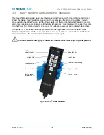
Page 22: ...he desired functions turn the Power Switch on and wait for 20 seconds for the table to power up and run its self diagnostics To operate any of the desired functions press and hold the appropriate button on the Hana Hand Pendant or Control Pad until the desired position is achieved See Figure 6 and the tables that follow for more information on the Hand Pendant functions and Indicator Lights CAUTIO...

Page 23: ...ral Tilt button to tilt the tabletop to the left until the desired position is achieved Right Lateral Tilt Press and hold the Right Lateral Tilt button to tilt the tabletop to the right until the desired position is achieved Return to Level Press and hold the Return to Level button to return the tabletop to a level position The tabletop will move in the following sequence 1 The tabletop will level...

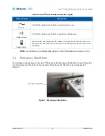
Page 24: ...tion of the arrows until it returns to its original position Figure 7 Figure 7 Emergency Stop Button Table 6 Hana Hand Pendant Indicator Lights Indicator Light Description AC Power This LED illuminates when the table is operating on AC power Battery Power This LED illuminates when the table is operating on battery power Battery Status When this LED illuminates green the battery is charged and the ...

Page 25: ...asters are in the locked position To engage the lock step on the foot pad and depress to the floor Figure 9 To unlock slide foot under the foot pad and lift to disengage the lock Figure 8 Figure 8 Caster in the Unlocked Position Figure 9 Caster in the Locked Position NOTE The casters and locks installed on your Hana Table may look different than those depicted above but they will operate in the sa...

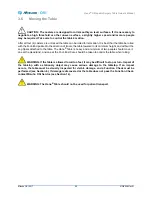
Page 26: ...ered to its minimum height and without the Leg Spars attached to the table The Hana Table is heavy and a minimum of two people should move it one at the Head End and one at the Foot End Care should be taken to control the table when rolling WARNING If the table is allowed to roll too fast it may be difficult to stop or turn Impact of the tabletop with a stationary object may cause serious damage t...

Page 27: ...ies for at least three 3 hours Place the table in an area with at least four 4 feet of clearance on all sides Perform a Function Check as described in Section 5 4 2 General Inspection Before use inspect the device for possible damage excessive wear or non functioning parts Visually inspect all accessible areas electrical cords and all movable parts for possible damage that may adversely affect the...

Page 28: ...er s Manual Mizuho OSI 2017 24 NW0508 Rev N 4 4 Preventative Maintenance Perform a Preventative Maintenance PM check on your Hana Orthopedic Surgery Table semi annually A PM checklist is available from Mizuho OSI Service see Section 14 ...

Page 29: ...attery OK or Battery Status light is on the table is ready to operate normally If the red Battery Charge light on the Control Panel or the red Battery Status light on the Hana Hand Pendant is on the battery must be charged prior to using the table To charge the battery make sure the Power Cord is plugged into a live receptacle and then turn on the Power Switch This switch will illuminate indicatin...

Page 30: ...turn to Level button Verify that the tabletop first levels from side to side and front to back and then after a 3 second delay the tabletop moves down to its lowest position 6 Perform a Control Panel check Repeat steps 5a through 5g using the Control Pad buttons 7 Perform a Femur Lift Control and Foot Pedal check a With Femur Lift Assembly connected to electricity the corresponding light on the Co...

Page 31: ...nt Safety Strap Pelvic Pad and Perineal Post Lateral Perineal Post and Board Assembly Traction Boots Traction Hook Extender Well Leg Support Assembly Hana Arm Boards Jack Mount Assembly Femur Lift s Coiled Hook Motor Cable s and Femur Lift Foot Pedal Femoral Hook Support and Femoral Hook s Hana Knee Flexion System 6 1 Hana Radiolucent Leg Spars The Hana Orthopedic Surgery Table is equipped with tw...

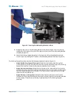
Page 32: ...the distal foot end of the Leg Spar by holding the Loop Handle while another person supports the proximal head end of the Leg Spar To install the Hana Radiolucent Leg Spars 1 Ensure that the Leg Spar is held firmly at both distal and proximal ends 2 Insert the proximal end of the left or right Leg Spar into the appropriate Spar Mount Figure 10 Figure 10 Mounting the Leg Spar 3 Slide the proximal e...

Page 33: ... the Leg Spar as needed and then return the Spar Lock Handle to the locked position 7 Before transferring the patient to the table install the approved Mizuho OSI Leg Spar Ball Joint Protectors Figure 12 CAUTION Failure to use the disposable Leg Spar Ball Joint Protectors may damage the ball joints on the Leg Spars and will void the warranty on the spars See Section 7 3 for ordering information Fi...

Page 34: ... desired position the Leg Spar can be locked to maintain that position A dial is provided to gauge the degree of internal and external rotation and should be zeroed out and locked in place utilizing the thumb screw when the foot is in the neutral position Gross and fine traction are also controlled near the Foot End of the Leg Spar Figure 13 Figure 13 Hana Radiolucent Leg Spar Controls The Tractio...

Page 35: ...nd then slide the entire assembly to the desired position When properly positioned turn the Gross Traction Knob clockwise to lock in place Figure 15 Figure 15 Leg Spar Gross Traction Adjustment To make fine traction adjustments turn the Fine Traction Crank Handle at the end of the Leg Spar to move the Traction Assembly to the desired position Rotate the Crank Handle clockwise to add traction Rotat...

Page 36: ...or the patient s height to allow operative traction to be applied and released using the Crank Handle for fine traction adjustments NOTE To allow the surgeon to pull adequate traction on the patient s legs during surgery the Hana Table is recommended for use on patients with a maximum inseam that does not exceed 43 inches Figure 17 Figure 17 Maximum Patient Inseam for Hana Table 43 inches ...
Page 37: ...he Leg Spar should be held securely by the Loop Handle at all times when it is not locked WARNING Adjusting Leg Spar position can affect traction Release the Gross Traction Knob while adjusting the Leg Spar position NOTE If the patient is short in stature and the Traction Brake Cover enters the Red Zone the installation and use of the Traction Hook Extender is required See Section 6 6 Figure 18 Sp...

Page 38: ...Hana Orthopedic Surgery Table Owner s Manual Mizuho OSI 2017 34 NW0508 Rev N Figure 19 Hana Orthopedic Surgery Table with Leg Spars Attached and Set Up for Anterior Approach Total Hip Replacement ...

Page 39: ...afety Strap 1 Slide the Patient Safety Strap around the Foot End of the Hana Table Figure 20 Figure 20 Patient Safety Strap Positioned on Hana Table 2 Once the patient is transferred to the table buckle the Patient Safety Strap around the patient at waist level and pull strap through the buckle until patient is secured firmly to the Hana Table Figure 21 Figure 21 Patient Secured to Table with Pati...

Page 40: ...rough the hole in the pad and into the attachment hole on the table 3 Move the patient to establish firm contact with the Perineal Post and then secure patient with the Patient Safety Strap and the associated Perineal Post WARNING After transferring the patient to the table assign at least one attendant to support the patient until safely secured to the table with the Patient Safety Strap and the ...

Page 41: ...teral Perineal Post and Board Assembly 1 Align the board holders on the Lateral Board around the left and right edges of the Foot End of the table top 2 Slide the Lateral Board toward the Head End of the table until it abuts the main table pad Figure 23 Ensure that the notch at the distal end of the pad aligns with the Perineal Post attachment hole Figure 23 Sliding Lateral Board in Place 3 Place ...

Page 42: ...th the Lateral Perineal Post and then secure patient with the Patient Safety Strap and the Lateral Perineal Post To remove the Lateral Perineal Post and Lateral Board Assembly 1 After removing anything securing the patient s arms and legs to the table remove the Patient Safety Strap and the Lateral Perineal Post 2 Upon removal of the Lateral Perineal Post immediately transfer the patient from the ...

Page 43: ...for more information Traction Boots are provided in two sizes small and large Extra large Traction Boots are also available as an optional accessory See Section 9 for more information Refer to the following size chart to select the appropriate Traction Boot Adjust the amount of padding as needed for the size of the patient s foot CAUTION When using the Traction Boots ensure that the proper size is...

Page 44: ...rs the Red Zone the installation and use of the Traction Hook Extender is required The Traction Hook Extender secures to the Leg Spar Traction Mount The Traction Boot attaches to the hook at the end of the Traction Hook Extender as shown in Figure 26 Figure 26 Using a Traction Hook Extender for Patients Short in Stature Traction Hook Extender Traction Brake Cover Red Zone ...

Page 45: ...perative leg when the patient is in the supine position Figure 27 Figure 27 Well Leg Support Assembly Well Leg Support Assembly Drop Handle for Securing Well Leg Support to Articulating Bracket Lower Collar Collar with Hook Drop Handle Articulating Bracket Drop Handle for Securing Articulating Bracket Position Drop Handle for Securing Articulating Bracket to Well Leg Support Adapter ...

Page 46: ... the proximal end of the Well Leg Support Adapter forward until it is fully engaged A click should be heard when the adapter is inserted past the safety latch 3 Lock in place by turning the Spar Locking Knob clockwise until tight Figure 29 Figure 29 Well Leg Support Adapter Locked in Place 4 Slide the Articulating Bracket onto the post at the distal end of the Well Leg Support Adapter Figure 30 an...

Page 47: ...e Well Leg Support Pad angle Rotate the drop handle under the Leg Pad counterclockwise to loosen the ball joint under the Leg Pad adjust the angle of the Well Leg Support Pad and then rotate the drop handle clockwise to lock in place Adjust the hook orientation Rotate the drop handle on the collar with the hook counter clockwise to loosen adjust the height and orientation of the hook and collar an...

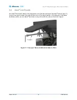
Page 48: ...Swing Bars on the left and right side of the Hana Table Figure 31 They can be used to support the patient s arms when in the supine position If the patient is in the lateral decubitus position use one Hana Arm Board in conjunction with the optional Cross Arm Support Figure 31 Close up of Hana Arm Board Installed on Table Swing Bar ...

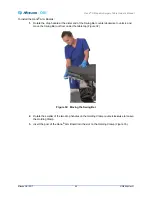
Page 49: ...istal end of the Swing Bar counterclockwise to unlock and move the Swing Bar out from under the table top Figure 32 Figure 32 Moving the Swing Bar 2 Rotate the smaller of the two drop handles on the Holding Clamp counterclockwise to loosen the Holding Clamp 3 Insert the post of the Hana Arm Board into the slot on the Holding Clamp Figure 33 ...

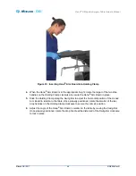
Page 50: ...a Arm Board in place 5 Slide the Holding Clamp along the Swing Bar to adjust the horizontal position of the Hana Arm Board in relation to the table Once properly positioned rotate the smaller of the two drop handles on the Holding Clamp clockwise to secure the clamp s position 6 Adjust the angle of the Hana Arm Board in relation to the table by moving the Swing Bar Once properly positioned rotate ...

Page 51: ...Hana Orthopedic Surgery Table Owner s Manual Mizuho OSI 2017 47 NW0508 Rev N Figure 34 Range of Motion of Swing Bar ...

Page 52: ...nt in place the Jack Mount may remain on the table The Jack Mount is located directly underneath the Foot End of the table top between the Spar Mounts WARNING Before use inspect the device for possible damage excessive wear or non functioning parts Visually inspect all accessible areas for possible damage that may adversely affect the proper operation of the Hana Orthopedic Surgery Table Damaged o...

Page 53: ...h Figure 36 Jack Mount Assembly Safety Latch Locked 2 Tighten the black knob to secure the Jack Mount assembly to the table Figure 36 3 When the black knob is firmly tight there should be minimal movement of the Jack Mount Assembly less than at the Jack Mount location Before every use visually inspect the safety latch lever and verify that it is fully engaged and hanging down Figure 36 Make sure t...

Page 54: ...atient Transfer Board is attached to the Jack Mount Assembly remove it See Section 9 3 2 for more information 4 To remove the Jack Mount Assembly loosen the black knob to fully disengage the threads Figure 36 5 Lift the safety latch to the unlocked position Figure 37 and pull forward on the Jack Mount Assembly The Jack Mount Assembly should slide off freely without excessive force Figure 37 Jack M...

Page 55: ...ch are located underneath the table top at the Foot End If the Circuit Breaker trips on either of the boxes Figure 38 the corresponding Femur Lift is powered off WARNING If the Circuit Breaker trips on the Left Right Expansion Junction Box during surgery the Femur Lift Emergency Crank Handle should be used to move the Femur Lift Resetting the Circuit Breaker and reusing the Foot Switch to operate ...

Page 56: ...c Surgery Table Owner s Manual Mizuho OSI 2017 52 NW0508 Rev N Figure 39 Expansion Junction Box Location 6 10 1 Connecting the Coiled Hook Motor Cable to the Expansion Junction Box Figure 40 Coiled Hook Motor Cables ...

Page 57: ...he plug aligns with the red dot on the Expansion Junction Box receptacle 3 Push the Coiled Hook Motor Cable s plug into the Expansion Junction Box s receptacle until it clicks 4 Repeat this procedure for the Expansion Junction Box on the other side Figure 41 Connecting the Coiled Hook Motor Cable to the Expansion Junction Box 6 10 2 Connecting the Coiled Hook Motor Cable to the Femur Lift To conne...

Page 58: ...emur Lift 4 Mount the Femur Lift into the Jack Mount Assembly and tighten the Femur Lift Lock Figure 43 Figure 43 Femur Lift Mounted on Jack Mount Assembly 5 Repeat this procedure for the Femur Lift on the other side Match the red dots Femur Lift Grooves Mount Femur Lift on Jack Mount Assembly Rotate Femur Lift Lock to tighten ...

Page 59: ...onnect Plugs 3 Unlock the Femur Lift Lock and remove the Femur Lift from the Jack Mount Assembly 4 Repeat this procedure for the Femur Lift on the other side If a complete removal of the Coiled Hook Motor Cable from the table is desired repeat step 1 for the other side of the electrical quick disconnect plug on the Expansion Junction Box Remove the Coiled Hook Motor Cable from the clip CAUTION Do ...

Page 60: ...setup perform the following steps to ensure that the Foot Pedal and Femur Lift function correctly 1 Verify that the Foot Pedal Connected LED is illuminated on the Control Panel Figure 4 2 On the Control Panel Figure 4 rotate the Selection Switch to select either the left or right Femur Lift 3 Verify that the corresponding LED illuminates indicating that the Femur Lift is properly connected 4 Press...

Page 61: ...r Lift Emergency Crank Handle is stored underneath the Head End of the tabletop Figure 46 Figure 46 Femur Lift Emergency Crank Handle Storage Location The Femur Lift Emergency Crank Handle is attached to the rear of the Femur Lift Assembly To operate the Femur Lift manually insert the Emergency Crank Handle into the opening and rotate the handle to move the Femur Lift up and down Figure 47 Figure ...

Page 62: ...ach use you must do the following Clean and sterilize the instrument s according to your hospital s washing decontamination and sterilization procedure If the Femoral Hook Support requires reassembly ensure that the bolt is fully seated i e torqued to 25 30 ft lbs or 35 40 Nm and that the hook bar can rotate freely around the post Inspect the Femoral Hook s and Femoral Hook Support for damage wear...

Page 63: ... Hook Support 2 Insert the sterilized left or right Femoral Hook in one of the notches on the Femoral Hook Support Select the notch based on the size and position of the patient that will allow the Femoral Hook to support the femur on the operative side during the procedure Figure 49 Figure 49 Femur Lift in Place for Use with the Femoral Hook Support and Femoral Hook 3 Use the Femur Lift Foot Peda...

Page 64: ...misuse will result in damage Before each use you must do the following Clean and sterilize the instrument according to your hospital s washing decontamination and sterilization procedure Inspect the Knee Flexion System for damage wear and functionality check for nicks burrs or bent parts Proper cleaning handling and sterilization will ensure that the Knee Flexion System performs as intended See Se...

Page 65: ...dle clockwise until it stops 3 Drape the operative side Leg Spar Clear sterile drapes are recommended to provide improved intraoperative visibility and accessibility 4 Maintaining sterile technique rotate the Clamp Knob counterclockwise to loosen the Attachment Brackets on the Knee Flexion System 5 Mount the Knee Flexion System on the Traction Assembly and rotate the Clamp Knob clockwise to tighte...

Page 66: ...gery Table Owner s Manual Mizuho OSI 2017 62 NW0508 Rev N Figure 52 Foot Plate Placed on the Foot Plate Holder Figure 53 Hana Orthopedic Surgery Table Set Up for Right TKA Leg Spar Draped Plate Position 1 Plate Position 2 ...

Page 67: ... Handle clockwise to secure the Foot Plate in position The Hana Knee Flexion System allows for full flexion extension of the leg and knee To obtain flexion of 120 or more attach the Foot Plate to Plate Position 2 as shown in Figure 55 To obtain flexion of 90 or less attach the Foot Plate to Plate Position 1 or to Plate Position 2 as shown in Figure 56 To further reduce flexion attach the Foot Plat...

Page 68: ...017 64 NW0508 Rev N Figure 55 Table Set Up for Total Knee Arthroplasty with Knee Flexion System Foot Plate in Position 2 Knee at 120 Flexion Figure 56 Table Setup for Total Knee Arthroplasty with Knee Flexion System Foot Plate in Position 2 Knee at 90 Flexion ...

Page 69: ...ic Surgery Table Owner s Manual Mizuho OSI 2017 65 NW0508 Rev N Figure 57 Table Setup for Total Knee Arthroplasty with Knee Flexion System Foot Plate in Position 1 Knee at Full Extension by Adjusting Gross Traction ...

Page 70: ... base of the table the Motion Control Box and tabletop It also includes the Hana Hand Pendant Jack Mount Assembly Main Table Pad and Pelvic Pad There are three versions of the Hana Table Base to accommodate different regional voltage requirements 6807 4 Hana Hand Pendant replacement part The Hana Hand Pendant controls the Hana Table functions including table top height Trendelenburg Reverse Trende...

Page 71: ...art The 2 inch 5 cm Hana Pelvic Pad is of TEMPUR construction It attaches to the Foot End of the table top and supports the patient s pelvis when positioned supine on the Hana Table 6850 413 Adult Perineal Post The Adult Perineal Post provides counter traction while the urethane foam pad helps relieve pressure on the perineal area The Adult Perineal Post is 9 inches long 22 8 cm and has a 2 75 inc...

Page 72: ...hen in the lateral decubitus position on the Hana Table 5840 44 Patient Safety Strap The Patient Safety Strap secures the patient in place when positioned on the table The 90 inch strap slides around the Foot End of the table 6875 2730 Jack Mount Assembly replacement part a 914 516 Drop Handle The Jack Mount Assembly attaches to underside of the tabletop and supports the left and right Femur Lifts...

Page 73: ...d A variety of disposable foam padding options for the Hana Arm Boards are available see Section 7 2 Hana Radiolucent Leg Spars Left and Right 6875 390 Left Backwards compatible with 6875 360 6875 370 Right Backwards compatible with 6875 350 a 6875 2370 Traction Unit Assembly b 6875 378 Foot Rotation Locking Knob c 6850 313 Fine Traction Crank Handle The Left and Right Hana Radiolucent Leg Spars a...

Page 74: ...tion 7 2 6875 399 Traction Hook Extender The Traction Hook Extender connects the Traction Boot to the Traction Unit of the Leg Spar for patients who are short in stature 6875 200 Well Leg Support Adapter The Well Leg Support Adapter attaches to the table and allows mounting of the Articulating Bracket and Well Leg Support Assembly which can be used to support the patient s non operative leg while ...

Page 75: ...ng Bracket It can be used to support the patient s non operative leg while in the supine position 6875 230 Hana Knee Flexion System a 6875 209 Knee Flexion Footplate Assembly b 6875 208 Knee Flexion Base Assembly The Hana Knee Flexion System is designed to mount on the operative Leg Spar to support and position the leg as needed during Total Knee Arthroplasty TKA It allows for full flexion extensi...

Page 76: ...ction 9 4 6875 264 Femur Lift Extension 2 The Femur Lift Extension attaches to either the left or right Femur Lift It provides the attachment point for the Femoral Hook Support 6875 602 Femur Lift Emergency Crank Handle The Femur Lift Emergency Crank Handle attaches to the rear of the Femur Lift Assembly It provides a manual method for raising and lowering the Femur Lift if there is a loss of powe...

Page 77: ...o one of the eight notches on the Femoral Hook Support The choice of Femoral Hook or Classic Femoral Hook is at the discretion of the surgeon and surgical team Classic Femoral Hooks Left and Right 6850 140 Classic Left 6850 144 Classic Right Two 2 Classic Femoral Hooks come standard with the Hana Table one left and one right The Femoral Hook is used during Anterior Approach Total Hip Arthroplasty ...

Page 78: ...nt Care Kit The Patient Care Kits are single use padding and covers intended to prevent cross contamination and protect the equipment Three 3 Patient Care Kits are included with the Hana Table See Section 7 3 for reordering information Table 7 Standard Components Continued Component Description ...

Page 79: ...ble components for the Hana Orthopedic Surgery Table Table 8 Disposable Components 5855 18 Soft Traction Boot Liners Small 24 per case 5855 17 Soft Traction Boot Liners Large 24 per case 5937DZ Disposable Boot Liners 12 per case good for all sizes of Traction Boots 6855 13 Perineal Post Cover Blue Foam 12 per case 5929DZ Perineal Post Cover 6 inch 12 per case 5823 10 Foam Arm Cradles 6 pairs per c...

Page 80: ...t Care Kits are single use only Discard after use Re use of any component in the Patient Care Kit may result in cross contamination The components should be used as described in the Patient Care Kit Instructions for Use which are included in each packaged kit The Hana Orthopedic Surgery Table ships with three 3 individual Hana Patient Care Kits A case of six 6 individual kits is provided when orde...

Page 81: ...eon and surgical team NOTE For the following setups use Patient Care Kit components as described in Instructions for Use included in each Kit A variety of additional soft goods are also available for use in all setups to ensure optimal patient comfort For more information see Section 7 2 and Section 7 3 Final determination of products used is at the discretion of the surgeon and surgical team NOTE...

Page 82: ...t Hana Radiolucent Leg Spars to the table and lock in place 4 Place the Pelvic Pad on the table 5 Attach the optional Hana Patient Transfer Board 6 Slide the Patient Safety Strap into place 7 Adjust the table to the appropriate height for patient transfer from the stretcher 8 Put the appropriate size Traction Boot small large or optional extra large on the patient s non operative foot while the pa...

Page 83: ...raction Mount If desired the optional 90 Degree Pin and Wire Holder or Kirschner Bow Holder may be used instead They require attaching a ProFx Traction Boot Adapter Assembly to the Leg Spar Traction Mount Position the patient s operative leg NOTE If the patient is short in stature and the Traction Brake Cover enters the Red Zone the installation and use of the Traction Hook Extender is required Se...

Page 84: ...Right IM Femoral Nailing Supine with Skeletal Traction Foot Secured to Leg Spar Components for Femur Nailing Supine with Skeletal Traction Jack Mount Assembly Hana Radiolucent Leg Spar Left and Right Pelvic Pad Hana Patient Transfer Board Optional Patient Safety Strap Traction Boot Left or Right Large or Small ...

Page 85: ... Optional Clark Socket Optional Traction Device Hook Optional 90 Degree Pin and Wire Holder Optional Kirschner Bow Holder Optional ProFx Traction Boot Adapter Assembly Optional Lower Leg Support Optional Accessory Clamp Optional Head End Drape Rod Assembly Optional Foot End Drape Rod Assembly Optional Components for Femur Nailing Supine with Skeletal Traction Continued ...

Page 86: ...right Hana Radiolucent Leg Spars to the table and lock in place 4 Place the Pelvic Pad on the table 5 Attach an Accessory Clamp to the operative side Leg Spar near the Foot End with the receiver on the non operative side of the table 6 Insert the optional Tibia Traction Upright into the Accessory Clamp from the bottom with the Traction Unit Receiver facing the operative side of the table 7 Attach ...

Page 87: ... Plate Assembly NOTE If using a Traction Boot on the operative foot instead attach the Traction Boot to the Tibial Traction Boot Adapter mounted on the Traction Unit 17 Install a Hana Arm Board with pad to both left and right sides of the table and position the patient s arms out to the side or attach one Hana Arm Board with pad and the optional Cross Arm Support using a Clark Socket to the non op...

Page 88: ...ecured to Optional Traction Foot Plate Assembly Components for Femur Nailing Supine with Skeletal Traction Jack Mount Assembly Hana Radiolucent Leg Spar Left and Right Pelvic Pad Accessory Clamp Optional Tibial Traction Upright Optional Traction Unit Optional Traction Foot Plate Assembly Optional Tibial Traction Boot Adapter Optional Hana Patient Transfer Board Optional ...

Page 89: ...ana Arm Board with Pad 2 Cross Arm Support Optional Clark Socket Optional Traction Device Hook Optional 90 Degree Pin and Wire Holder Optional Kirschner Bow Holder Optional ProFx Traction Boot Adapter Assembly Optional Lower Leg Support Optional Head End Drape Rod Assembly Optional Foot End Drape Rod Assembly Optional Components for Femur Nailing Supine with Skeletal Traction Continued ...

Page 90: ...table on the operative side and lock in place 4 Place the Pelvic Pad on the table 5 Attach the optional Hana Patient Transfer Board 6 Slide the Patient Safety Strap into place 7 Adjust the table to the appropriate height for patient transfer from the stretcher 8 Put the appropriate size Traction Boot small large or optional extra large on the patient s operative foot while the patient is on the st...

Page 91: ...ft and right sides of the table and position the patient s arms out to the side or attach one Hana Arm Board with pad and the optional Cross Arm Support using a Clark Socket to the non operative side of the table Secure the patient s arms 15 Remove the optional Hana Patient Transfer Board by sliding it out from underneath the fully positioned patient 16 If desired attach the optional Lower Leg Sup...

Page 92: ...Patient Transfer Board Optional Patient Safety Strap Traction Boot Left or Right Large or Small Perineal Post Traction Hook Extender Well Leg Support Adapter Articulating Bracket Well Leg Support Assembly Hana Arm Board with Pad 1 or 2 Cross Arm Support Optional Clark Socket Optional Lower Leg Support Optional Accessory Clamp Optional Head End Drape Rod Assembly Optional Foot End Drape Rod Assembl...

Page 93: ...nt Assembly is installed 3 Attach both the left and right Hana Radiolucent Leg Spars to the table and lock in place 4 Attach the Lateral Board Assembly without Lateral Perineal Post to the table top by sliding it into position and inserting the plug into the standard Perineal Post hole on the table top 5 Slide the Patient Safety Strap into place 6 Attach the optional Hana Patient Transfer Board 7 ...

Page 94: ...tive side Leg Spar NOTE If the patient is short in stature and the Traction Brake Cover enters the Red Zone the installation and use of the Traction Hook Extender is required See Section 6 6 for more information 14 Install a Hana Arm Board with pad and optional Cross Arm Support using a Clark Socket to the non operative side of the table and secure the patient s arms 15 Remove the optional Hana Pa...

Page 95: ... Radiolucent Leg Spar Left and Right Lateral Perineal Post and Board Assembly Patient Safety Strap Hana Patient Transfer Board Optional Traction Boot Pair Large or Small Traction Hook Extender Hana Arm Board with Pad Cross Arm Support Optional Clark Socket Optional Lower Leg Support Optional Accessory Clamp Optional Head End Drape Rod Assembly Optional Foot End Drape Rod Assembly Optional ...

Page 96: ... Lift Assembly right or left to the operative side of the table 3 Plug the Femur Lift Foot Pedal into the front of the base of the table Ensure that the Femur Lift Assembly is in its lowest position 4 Place the Pelvic Pad on the table 5 Slide the Patient Safety Strap in place 6 Attach the optional Hana Patient Transfer Board 7 Adjust the table to the appropriate height for patient transfer from th...

Page 97: ...g Spar Mount on the non operative side of the table and lock into position 12 Attach the Well Leg Support Assembly to the Well Leg Support Adapter using the Articulating Bracket and secure the patient s non operative leg 13 Install a Hana Arm Board with pad to both left and right sides of the table and position patient s arms out to the side or attach one Hana Arm Board with Pad and the optional C...

Page 98: ... Assembly Femur Lift Assembly Left or Right Femur Lift Foot Pedal Pelvic Pad Patient Safety Strap Hana Patient Transfer Board Optional Perineal Post Lateral Perineal Post Optional Lateral Perineal Post Adapter Optional Well Leg Support Adapter Well Leg Support Assembly Articulating Bracket Hana Arm Board with Pad 1 or 2 Cross Arm Support Optional Clark Socket Optional ...

Page 99: ...ach the appropriate left or right Hana Radiolucent Leg Spar on the operative side of the table and lock in place 4 Plug the Femur Lift Foot Pedal into the front of the base of the table Ensure that the Femur Lift Assembly is in its lowest position 5 Place the Pelvic Pad on the table 6 Attach an Accessory Clamp to the operative side Leg Spar near the Foot End with the receiver on the non operative ...

Page 100: ...urological or circulatory injury 16 Secure the patient s operative foot to the Traction Foot Plate Assembly NOTE Before making any height adjustments to the Lateral Perineal Post using the Femur Lift Assembly be sure to remove the operative foot from the Traction Foot Plate Assembly Once height adjustments have been made re secure the foot to the Traction Foot Plate Assembly 17 Attach the Well Leg...

Page 101: ...with Unilateral Skin Traction Components for Retrograde IM Femoral Nailing Supine with Unilateral Skin Traction Jack Mount Assembly Hana Radiolucent Leg Spar Left and Right Femur Lift Assembly Left or Right Femur Lift Foot Pedal Pelvic Pad Accessory Clamp Optional Tibial Traction Upright Optional Traction Unit Optional Traction Foot Plate Assembly Optional ...

Page 102: ...onal Perineal Post Lateral Perineal Post Optional Lateral Perineal Post Adapter Optional Well Leg Support Adapter Well Leg Support Assembly Articulating Bracket Hana Arm Board with Pad 1 or 2 Cross Arm Support Optional Clark Socket Optional Components for Retrograde IM Femoral Nailing Supine with Unilateral Skin Traction Continued ...

Page 103: ...bly is installed 3 Attach the operative side Hana Radiolucent Leg Spar left or right to the table and lock in place 4 Place the Pelvic Pad on the table 5 Slide the Patient Safety Strap in place 6 Attach the Well Leg Support Adapter into the Leg Spar Mount on the non operative side of the table and lock into position 7 Attach the optional Hana Patient Transfer Board 8 Adjust the table to the approp...

Page 104: ...ulating Bracket and secure the patient s non operative leg 14 Install a Hana Arm Board with pad to both right and left sides of the table and position the patient s arms out to the side or attach one Hana Arm Board with pad and the optional Cross Arm Support using a Clark Socket to the non operative side of the table Secure the patient s arms 15 Remove the optional Hana Patient Transfer Board by s...

Page 105: ...lvic Pad Patient Safety Strap Well Leg Support Adapter Hana Patient Transfer Board Optional Traction Boot Left or Right Large or Small Perineal Post Traction Hook Extender Well Leg Support Assembly Articulating Bracket Hana Arm Board with Pad 1 or 2 Cross Arm Support Optional Clark Socket Lower Leg Support Optional Accessory Clamp Optional Head End Drape Rod Assembly Optional Foot End Drape Rod As...

Page 106: ...ly is installed 3 Attach both left and right Hana Radiolucent Leg Spars to the table and lock in place 4 Place the Pelvic Pad on the table 5 Attach the optional Hana Patient Transfer Board 6 Slide the Patient Safety Strap in place 7 Adjust the table to the appropriate height for patient transfer from the stretcher 8 Put the appropriate size Traction Boots small large or optional extra large on the...

Page 107: ...rms out to the side or attach one Hana Arm Board with pad and the optional Cross Arm Support using a Clark Socket to the non operative side of the table Secure the patient s arms 13 Remove the optional Hana Patient Transfer Board by sliding it out from underneath the fully positioned patient 14 If desired attach the optional Lower Leg Support to the operative or non operative Leg Spar using an Acc...

Page 108: ...cent Leg Spar Left and Right Pelvic Pad Hana Patient Transfer Board Optional Patient Safety Strap Traction Boot Pair Large or Small Perineal Post Traction Hook Extender Hana Arm Board with Pad 1 or 2 Cross Arm Support Optional Clark Socket Optional Lower Leg Support Optional Accessory Clamp Optional Head End Drape Rod Assembly Optional Foot End Drape Rod Assembly Optional ...

Page 109: ...ion 10 2 These items attach to the top of the appropriate Femur Lift Assembly 1 Ensure all four 4 Casters are in the locked position 2 Ensure that the Jack Mount Assembly is installed 3 Ensure that both the left and right Hana Radiolucent Leg Spars are attached to the table and locked in place 4 Place the Pelvic Pad on the table 5 Plug the Femur Lift Foot Pedal into the front of the base of the ta...

Page 110: ...n Brake Cover enters the Red Zone the installation and use of the Traction Hook Extender is required See Section 6 6 for more information 14 Install a Hana Arm Board with pad to both left and right sides of the table and position the patient s arms out to the side or attach one Hana Arm Board with pad and the optional Cross Arm Support using a Clark Socket to the non operative side of the table Se...

Page 111: ... Leg Spar Left and Right Pelvic Pad Femur Lift Foot Pedal Femur Lift Assembly Patient Safety Strap Hana Patient Transfer Board Optional Traction Boot Pair Large or Small Perineal Post Traction Hook Extender 2 Hana Arm Board with Pad 2 Cross Arm Support Optional Clark Socket Optional Lower Leg Support Optional Accessory Clamp Optional Femoral Hook Support Femoral Hooks ...

Page 112: ...lled 3 Ensure that both the left and right Hana Radiolucent Leg Spars are attached to the table and locked in place NOTE Optionally the non operative leg may be supported using the Well Leg Support Assembly instead of the Hana Radiolucent Leg Spar 4 Place the Pelvic Pad on the table 5 Slide the Patient Safety Strap in place 6 Attach the optional Hana Patient Transfer Board 7 Adjust the table to th...

Page 113: ...ion and use of the Traction Hook Extender is required See Section 6 6 for more information 12 Install a Hana Arm Board with pad to both left and right sides of the table and position the patient s arms out to the side or attach one Hana Arm Board with pad and the optional Cross Arm Support using a Clark Socket to the non operative side of the table Secure the patient s arms 13 Remove the optional ...

Page 114: ...ly Hana Radiolucent Leg Spar Left and Right Pelvic Pad Patient Safety Strap Hana Patient Transfer Board Optional Traction Boot Pair Large or Small Large Diameter Perineal Post Traction Hook Extender 2 Hana Arm Board with Pad 2 Cross Arm Support Optional Clark Socket Optional Lower Leg Support Optional Accessory Clamp Optional ...

Page 115: ...er to the non operative side of the table and lock in place 4 Attach the Articulating Bracket to the Well Leg Support Adapter and tighten securely 5 Insert the Well Leg Support Assembly into the Articulating Bracket and tighten securely 6 Place the Pelvic Pad on the table If extra support is desired slide the Lateral Board Assembly without Lateral Perineal Post on the table instead 7 Slide the Pat...

Page 116: ...eg Spar and attach the sterilized Knee Flexion System to the Leg Spar 13 Place the operative foot on the Foot Plate of the Knee Flexion System and secure according to surgeon protocol Figure 79 Patient Positioned for Total Knee Arthroplasty with Well Leg Support Assembly Components for Total Knee Arthroplasty with Well Leg Support Assembly Hana Radiolucent Leg Spar Left or Right Well Leg Support A...

Page 117: ...l Knee Arthroplasty with Left and Right Leg Spars NOTE Each number in the setup image identifies the component s described in the corresponding step in the following setup instructions Patient Safety Strap Perineal Post Hana Arm Board with Pad 2 Hana Knee Flexion System Components for Total Knee Arthroplasty with Well Leg Support Assembly Continued 1 2 3 8 10 11 9 4 ...

Page 118: ...ile the patient is on the stretcher 7 Transfer the patient to the table in the supine position and secure the patient with the Patient Safety Strap 8 Insert the padded Perineal Post into the table Move the patient to establish firm contact with the Perineal Post and adjust the Patient Safety Strap as appropriate 9 Attach the Traction Boot on the non operative leg to the Traction Mount on the non o...

Page 119: ...8 Rev N Components for Total Knee Arthroplasty with Left and Right Leg Spars Hana Radiolucent Leg Spar Left and Right Pelvic Pad Lateral Board Patient Safety Strap Traction Boot Left or Right Large or Small Perineal Post Hana Arm Board with Pad 2 Hana Knee Flexion System ...

Page 120: ...ns the Hana Patient Transfer Board is removed The Hana Patient Transfer Board comes with a 3 inch 7 6 cm Tempur Pedic Medical Pad This optional accessory may also be ordered separately 6875 747 Head End Drape Rod Assembly a Modified Clark Socket If Patient Isolation Drapes are to be used they can be supported on both Head End and Foot End Drape Rod Assemblies The Head End Drape Rod Assembly includ...

Page 121: ...unt Bracket for Lateral Perineal Post also included in this kit It can be used to provide counter traction in IM Femoral and Tibial Nailing surgical procedures The Perineal Post is 15 inches long 38 1 cm and has a 2 75 inch 7 cm diameter with pad 6850 114 Traction Device Hook The Traction Device Hook attaches to the Leg Spar Traction Mount and may be used in procedures requiring skeletal traction ...

Page 122: ... Hana Table Fracture Kit See Section 9 1 for more information on the kit 3369 Large Diameter Perineal Post The Large Diameter Perineal Post provides counter traction while the urethane foam pad helps relieve pressure on the perineal area It may be used in place of the Adult Perineal Post that comes standard with the table if desired The Perineal Post is 9 inches long 22 8 cm and has a 6 inch 15 2 ...

Page 123: ...ith Pad The Cross Arm Support may be mounted onto the Hana Table using a Clark Socket to support the patient s arm over his or her chest This accessory comes with a one inch 2 5 cm Tempur Pedic Medical Pad 5393 Clark Socket The Clark Socket attaches to the side rail of the Hana Table to facilitate attachment of additional accessories including the Cross Arm Support 6300 93 90 Degree Pin and Wire H...

Page 124: ...oral Nailing procedures 5855 345 Traction Unit The Traction Unit attaches to the Tibia Traction Upright and provides fine traction adjustment The Traction Foot Plate Assembly can be attached directly to the Traction Unit The Traction Boot can be attached to the Traction Unit with the Tibial Traction Boot Adapter 5855 440 Traction Foot Plate Assembly The Traction Foot Plate Assembly can be used to ...

Page 125: ...eg Spar with an Accessory Clamp It can be used to provide additional support for the patient s operative leg This accessory comes with a one inch 2 5 cm Tempur Pedic Medical Pad 5855 61 Accessory Clamp The Accessory Clamp attaches to the Hana Radiolucent Leg Spar allowing various accessories to be mounted 6875 500 Hana Equipment Cart The Hana Equipment Cart may be used to store Hana Table componen...

Page 126: ...edge a cradle block and a rectangular pad to assist with patient positioning 10706 Orange Aid Universal Traction Boot Liner This reusable Traction Boot liner may be used with all sizes of Traction Boots available with the Hana Table The liner helps cushion the patient s foot when inside the Traction Boot 10704 Orange Aid Universal Perineal Post Pad This reusable 11 x 9 x 3 8 pad helps prevent pote...

Page 127: ...during the surgery The Hana Patient Transfer Board may be installed and removed under the following conditions With the Leg Spars either on the table or off the table With one Leg Spar and Well Leg Support Assembly installed With or without the Femur Lift Assembly installed With the Lateral Board and Lateral Perineal Post installed With or without a patient on the table in any of the above setup s...

Page 128: ...Hana Patient Transfer Board by the hard plastic top and guide the long arms into the guide fins on the Jack Mount Assembly The Hana Patient Transfer Board will stop when the small bolt on the bottom of the long arms contacts the front of the guide fin When fully installed there should be a slight gap between the Hana Patient Transfer Board and the table top Figure 83 Hana Patient Transfer Board Re...

Page 129: ...pads may be slightly out of alignment when the Hana Patient Transfer Board is installed Figure 85 Hana Patient Transfer Board Installed 9 3 2 Removing the Hana Patient Transfer Board from the Table To remove the Hana Patient Transfer Board 1 Remove the 3 inch Tempur Pedic pad from the Hana Patient Transfer Board 2 Grasp the Hana Patient Transfer Board by the hard plastic top and pull distally and ...

Page 130: ...l Post Installed on Femur Lift Assembly To install the Lateral Perineal Post 1 Ensure the Femur Lift Assembly is properly set up and powered as described in Section 6 10 2 Attach the Mount Bracket for the Lateral Perineal Post to the top of the Femur Lift Assembly Rotate the lower T Handle on the Mount Bracket to secure it to the Femur Lift Assembly Figure 87 3 Attach the Lateral Perineal Post to ...

Page 131: ...9 Lock Knob on Mount Bracket b Adjust the angle of the Lateral Perineal Post as needed c Rotate the Lock Knob on the Mount Bracket clockwise to secure in the new position WARNING It is important that the Lateral Perineal Post be placed against the distal femur two to three inches proximal to the popliteal fossa Placement of the post into the fossa may result in a potential neurological or circulat...

Page 132: ...k Socket Turn the Clark Socket handle clockwise to secure the Cross Arm Support upright Figure 90 Figure 90 Cross Arm Support Mounted to Table with a Clark Socket 3 Insert the Cross Arm Support into the Cross Arm Support upright and secure by turning the black knob clockwise 4 Position the Cross Arm Support over but not in contact with the patient s chest 5 Pad and secure the patient s arm to the ...

Page 133: ...e the Accessory Clamp on the appropriate Hana Radiolucent Leg Spar with the black knob facing down and the receiver on the non operative side of the table 2 Rotate the black knob clockwise to secure the clamp in place 3 Insert the Lower Leg Support Assembly in the Accessory Clamp 4 Rotate the T Handle on the clamp clockwise to secure the Leg Support Assembly in place Black Knob Accessory Clamp T H...

Page 134: ...is configuration of optional accessories can provide proximal and distal traction at the same time if desired Figure 92 Tibial Traction Assembly Attached to Leg Spar Figure 93 Tibial Traction Assembly Attached to Leg Spar and Using Secondary Skeletal Traction 90 Degree Pin and Wire Holder Foot Plate attached to Tibial Traction Assembly Traction Boot attached to Tibial Traction Assembly Accessory C...

Page 135: ... 4 Attach the Traction Unit to the Tibia Traction Upright 5 If using the Traction Boot a Attach the Tibial Traction Boot Adapter to the Traction Unit b Rotate the Gold Handle on the Traction Unit clockwise to secure the adapter c Once the patient has been transferred and secured to the table attach the Traction Boot to the Tibial Traction Boot Adapter 6 If using the Traction Foot Plate Assembly a ...

Page 136: ...mblies at the Head End and Foot End of the Hana Table Figure 94 Figure 94 Head End and Foot End Drape Rod Assemblies Attached to Table 9 8 1 Head End Drape Rod Assembly To attach the Head End Drape Rod Assembly 1 Slide the Modified Clark Socket on the table side rail at the Head End of the Hana Table Figure 95 Figure 95 Attaching Modified Clark Socket to Side Rail ...

Page 137: ...he Modified Clark Socket and rotate the T Handle on the Clark Socket clockwise to secure the Upright in place Figure 96 Figure 96 Securing Drape Hanger Upright into Modified Clark Socket 3 Attach the Head End Drape Hanger Top Rail to the top of the Drape Hanger Upright and position over the table as shown in Figure 94 ...

Page 138: ...de of the table Figure 97 Figure 97 Attaching Attachment Clamp Assembly to Leg Spar 2 Rotate the black knob clockwise to secure the clamp in place 3 Insert the Drape Hanger Upright into the Attachment Clamp Assembly and rotate the T Handle on the Clamp to secure the Upright in place Figure 98 Drape Hanger Upright Secured to Attachment Clamp Assembly 4 Attach the Foot End Drape Hanger Top Rail to t...

Page 139: ...na Equipment Cart may be used to store the Hana Table components and accessories when not in use The Equipment Cart Cover provided with the Cart serves as a dust cover and should be used while the products are in storage Figure 99 Equipment Cart Front and Back Empty Figure 100 Equipment Cart Front and Back Loaded ...

Page 140: ...ng or discoloration of plated or stainless steel surfaces clean with a good commercial cleaning compound labeled for stainless steel and then buff the surface by hand To disinfect exterior surfaces use a quaternary ammonium compound according to manufacturer s directions for use Wipe dry with a soft lint free cloth NOTE Failure to thoroughly dry the surface after cleaning and disinfecting may resu...

Page 141: ... or abrasive detergents Use of anything other than high quality brushes designed for surgical instrument cleaning may result in damage Disassembly of the Femoral Hook Support before cleaning is not necessary unless severely soiled or dictated by hospital policy Do not use high acid pH 4 or lower or high alkaline pH 10 or higher disinfectant products such as bleach and bi chloride of mercury 10 1 4...

Page 142: ...y years of trouble free service All components are lubricated for life at the factory and no other lubrication for the table is required Preventative Maintenance Contact Mizuho OSI Service for a complete preventative maintenance checklist For detailed repair information or to order replacement parts call or contact via the web Mizuho OSI Service 1 800 777 4674 Option 2 calls within the USA Or 1 51...

Page 143: ...220 230V 50 60Hz 2 5A and 10 6 minute duty cycle as indicated on the serial number label Refer to the Hana Table Electrical Interconnect Diagram in Section 13 2 for details on the electrical system The primary components of the electrical control system are contained in the Motion Control Box at the Head End of the table Electric motor driven lead screw type actuators Manipulate the Height Lateral...

Page 144: ...on 11 3 On Off Circuit Breaker Power Switch An illuminated On Off Power Switch and Circuit Breaker is located on the Head End of the table When illuminated it indicates that the table is plugged into a live electrical AC outlet and the power is on NOTE When the Power Switch is toggled On and the table is operating under battery power this switch will not illuminate This switch also serves as a Cir...

Page 145: ...es NV0801 Due to the relatively low power consumption of the Hana Table it can be used on battery power for up to 12 hours at 10 duty cycle CAUTION Whenever servicing the table personnel are required to wear personal protective equipment work jackets leather gloves and safety glasses whenever moving or removing parts and or components or replacing sheet metal covers WARNING This symbol indicates a...

Page 146: ...five 5 years Whenever the battery cover is opened check the battery for signs of corrosion The battery terminals should be clean and free from corrosion oil grease dirt or other contaminants Battery ordering number NV0801 NOTE Failure to use an approved Mizuho OSI battery voids the warranty and can cause harm to the table CAUTION Battery life can be shortened if the table remains unplugged and tur...

Page 147: ...ana Hand Pendant control buttons and light will be illuminated 3 Verify that the Circuit Breaker that is part of the Power Switch located at the base of the Motion Control Box is not tripped indicating table power overload To reset the Circuit Breaker toggle the Power Switch off and then on 4 Verify the Component Circuit Breakers located at the base of the Motion Control Box are not tripped indica...

Page 148: ... battery light illuminates 6 If the problem persists call Mizuho OSI Service 1 800 777 4676 Option 2 within the USA 1 510 429 1500 Option 2 outside the USA The Return to Level function is not operational 1 Verify the Power Cord is plugged into an appropriate AC receptacle and into the Power Cord receptacle located on table base panel 2 Press and hold the Return to Level button on the Hana Hand Pen...

Page 149: ...ical position drifting downward 1 Verify that the Spar Lock Handle is rotated clockwise to the locked position 2 Verify that the Leg Spar is securely attached fully seated and locked to the table 3 With wear the Spar Lock Handle may require adjustment to allow adequate movement to the lock position to hold the leg spar Adjust the Spar Ball Joint Lock Handle lock position as needed 4 If the problem...

Page 150: ...424 Drop Handle on Swing Bars 914 516 Batteries 2 Required NV0801 Caster 4 Required ND0451 Caster Washer 16 Required AE040081A Caster Screw 16 Required AABB075AAC Caster Rubber Cap 8 Required NB0375 Gimbal Kit 6875 9250 Top Cover Left 6875 85 Top Cover Right 6875 86 Column Cover Base 6875 79 Column Cover Mid Low 6875 80 Column Cover Mid High 6875 81 Column Cover Spacer Teflon 16 Required 6875 87 C...

Page 151: ...5 310 Spar Pressure Arm 2 per Spar 6850 267 Spar Locking Knob 2 Required 6875 325 Traction Unit Assembly 2 Required 6875 2370 Foot Rotation Locking Knob on Traction Unit 6875 378 Fine Traction Crank Handle on Traction Unit 6850 313 Rotation Brake Pad 6875 376 Gross Traction Brake Assembly Left 6875 9001 Gross Traction Brake Assembly Right 6875 9002 Gross Traction Bearing Carriage 1 per Spar NA0210...

Page 152: ...Hana Orthopedic Surgery Table Owner s Manual Mizuho OSI 2017 148 NW0508 Rev N 13 2 Interconnect Diagram 100V 120V 220 230V Models ...

Page 153: ...rvice before placing an order Once the part number is obtained follow the instructions below to order the replacement part If part is known please telephone fax or e mail part number and description to Mizuho OSI Service for price and availability To place a Replacement Parts RP order please telephone fax or e mail Mizuho OSI Service with the part number description price customer number and metho...

Page 154: ...rtificate of Decontamination with the shipment The part will be evaluated and the customer will be contacted with the cost of repair if not covered under table warranty After customer approval of repair cost the part will be repaired and returned to the customer 14 5 Warranty Mizuho OSI products come with a one 1 year warranty against manufacturer defect All expenses for parts and labor for produc...

Page 155: ...nt guidance RF emissions CISPR 11 Group 1 The Hana Table uses RF energy only for its internal function Therefore its RF emissions are very low and are not likely to cause any interference in nearby electronic equipment RF emissions CISPR 11 Class A The Hana Table is suitable for use in all establishments other than domestic establishments and those directly connected to the public low voltage powe...

Page 156: ...l environment Surge IEC 61000 4 5 1 kV line s to line s 2 kV line s to earth 1 kV line s to line s 2 kV line s to earth Mains power quality should be that of a typical commercial or hospital environment Voltage dips short interruptions and voltage variations on power supply input lines IEC 61000 4 11 5 UT 95 dip in UT for 0 5 cycle 40 UT 60 dip in UT for 5 cycles 70 UT 30 dip in UT for 25 cycles 5...

Page 157: ...fixed RF transmitters as determined by an electromagnetic site survey a should be less than the compliance level in each frequency range b Interference may occur in the vicinity of equipment marked with the following symbol Note 1 At 80 MHz and 800 MHz the higher frequency range applies Note 2 These guidelines may not apply in all situations Electromagnetic propagation is affected by absorption an...

Page 158: ...ications equipment Rated maximum output power of transmitter W Separation distance according to frequency transmitter m 150 kHz to 80 MHz 80 MHz to 800 MHz 800 MHz to 2 5 GHz 0 01 0 12 0 12 0 23 0 1 0 37 0 37 0 74 1 1 2 1 2 2 3 10 3 7 3 7 7 4 100 12 12 23 For transmitters rated at a maximum output power not listed above the recommended separation distance d in meters m can be estimated using the e...

Reviews: