7
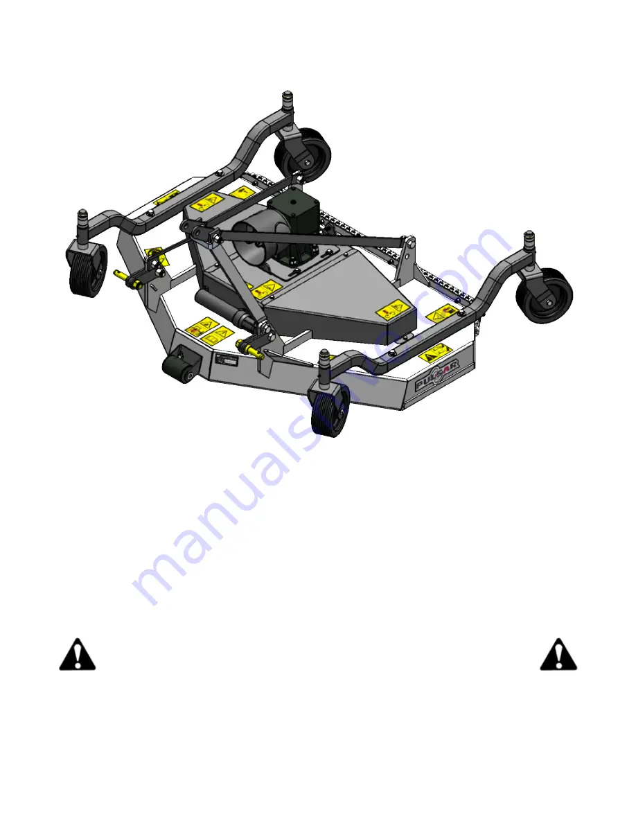
These Finish Mowers are shipped with the “A” Frame disassembled.
Assemble by undoing the top “A” Frame bolt and inserting the Brace Bars as shown above.
After tightening the nut on the bolt, back the nut off 1/3-1/2 turn to allow some movement in the
linkage.
Ensure the Anti-Scalp roller turns free, a few drops of oil my be added on the axle shaft at this
time.
Ensure the wheels and the caster pivot turn freely. Lightly grease the caster pivot.
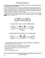
When attaching Mower to tractor ensure drive-line is the right length and does not bind.
(See page 22 for directions)
Assembly Information
THIRD ANGLE PROJECTION
5
4
3
1
Folder
S:\Solidworks\Solidworks_Elo\Finish Mower\EURO Finishing Mower\60 Finishing Mower\60 Rear Discharge\53285.SLDASM
DWG. NO.
REV
Model
SCALE 1:24
SHEET 3 OF5
DATE DRAWN
MATERIAL
53285
May-17-16 10:54:20 AM
DESCRIPTION
Finishing Mower 60 rear
S:\Solidworks\Solidworks_Elo\Finish Mower\EURO Finishing Mower\60 Finishing Mower\60 Rear Discharge\
Weight(lbs.)
0
Width
Height
Length
0
0
422.75
0
Blank Size
Unit of Measure
ITEM ID.
53285
Config ID
53285
DIMENSIONS ARE IN INCHES
TOLERANCES NON SPECIFIED:
FRACTIONAL 1/64
BEND 1.0
TWO PLACE DECIMAL 0.01"
THREE PLACE DECIMAL 0.002"
Notes
DO NOT SCALE DRAWING


