background image

Edition 1.03

Camera system

messtechnik

EMC Test and Measuring Systems

mk

Extended Manual

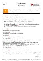
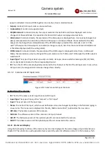
With button 

[1]

 you can turn the backlight adjustment on or off. Buttons 

[2]

 and 

[3]

 mirror the image horizontally 

and vertically. The whitebalance can be adjusted by using the values from the dropdown list 

[4]

 ,exposure mode 

with dropdown list 

[5]

. Contrast and sharpness are adjusted using the sliders 

[6]

 and 

[7]

 , electronical gain by 

using slider 

[8]

. With slider 

[9] 

you can adjust the shutter speed, provided you have selected the correct exposure 

mode. Color hue and color gain can be adjusted using scrollbars 

[10]

 and 

[11]

.

Using buttons 

[12]

 you can save your settings in the camera, reset them or set them to their default values.

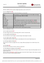
4.3.5 Expert Settings

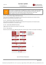
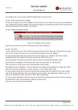
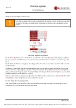
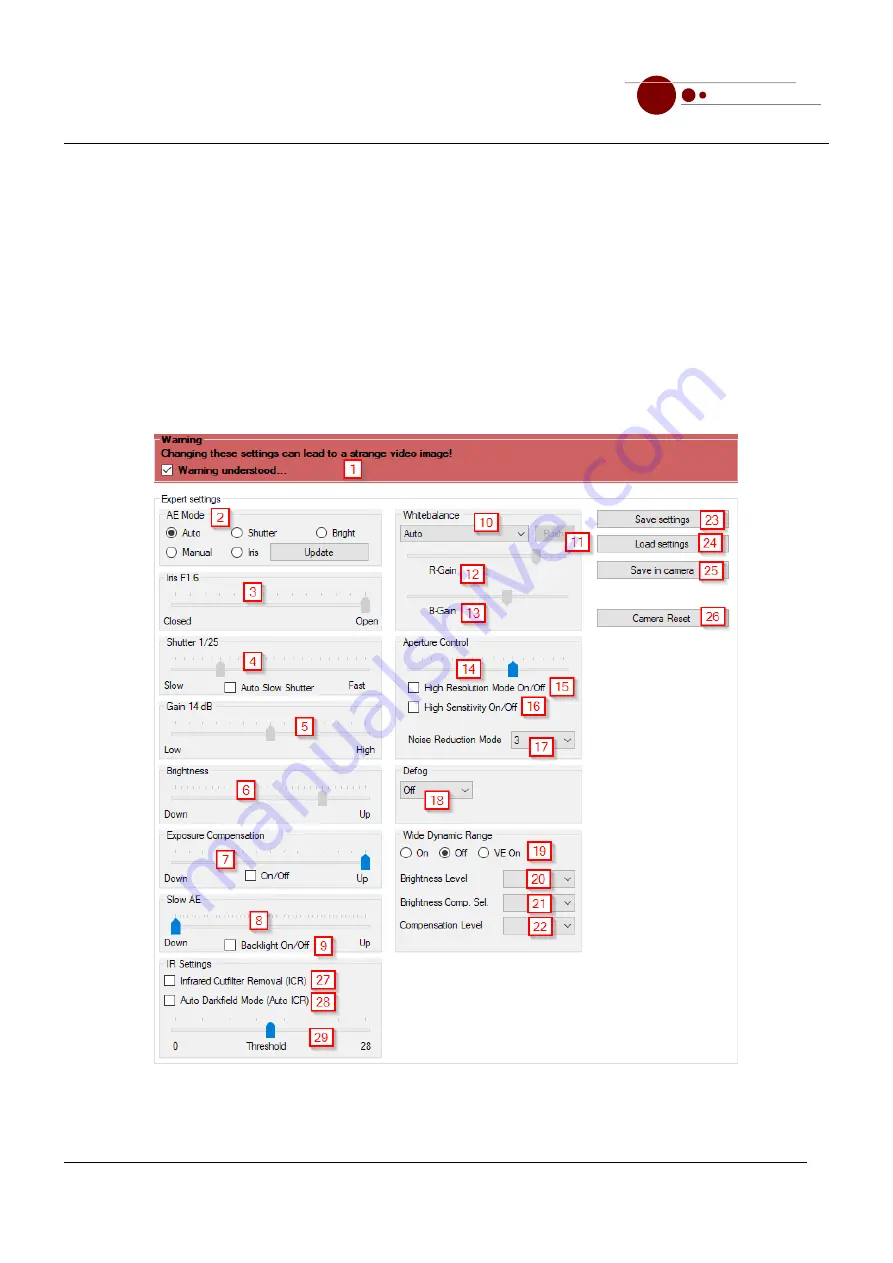
With these functions many settings can be done directly in the camera module. This is especially useful in bad or 
unusual lighting situations or when using a motion detection software. Since extensive knowledge of cameras in 
general is needed to use these functions reasonably, you first have to confirm a warning message 

[1]

!

Figure 4-11: Expert Settings

Page 20 / 43

Distributed by: Reliant EMC LLC, 3311 Lewis Ave, Signal Hill CA 90755, 408­916­5750, www.reliantemc.com


Summary of Contents for DAV-CR Series

Page 1: ...Interfaces Camera Control Software On Screen Display Extended Manual Camera system with digital transmission of analogue A V signals Distributed by Reliant EMC LLC 3311 Lewis Ave Signal Hill CA 90755...

Page 2: ...Actual Pan Tilt Unit Position and Camera Zoom 17 4 3 4 Standard Settings 17 4 3 5 Expert Settings 20 4 3 6 Matrix Connections 23 4 3 7 Information 24 4 3 8 On Screen Display 25 4 3 9 Configuration 30...

Page 3: ...extended manual is only valid in combination with the base manual Follow all instructions of the base manual In particular follow the safety instructions of the base manual Disregard can lead to hazar...

Page 4: ...ns can be equipped with different connectors 2 2 1 Optical Input AV Output Card This card contains depending on the selected options one VGA DVI HDMI output one SDI output one CVBS video output and or...

Page 5: ...4 Connectors and operating controls of the AV input card 2 2 2 1 Selection of the Video Input The AV input channel contains two physical connectors DVI and Cinch for the video input You can connect a...

Page 6: ...75 Hz X X 800 x 600 56 Hz 60 Hz 70 Hz 75 Hz X X 720 x 480 60 Hz X X 60 Hz Interlaced X 720 x 576 50 Hz X X 50 Hz Interlaced X 640 x 480 60 Hz 72 Hz 75 Hz X X Table 2 1 Supported input resolutions and...

Page 7: ...for VGA This way it recognizes an analog monitor and therefore does not send DVI video signals If the AV input card is switched to DVI the DVI source still won t send a signal because it does not re...

Page 8: ...iver must be configured as a client using the Camera Control Software see chapter 4 3 9 3 There is exactly one TCP IP connection between the source and target receivers at the same time regardless of...

Page 9: ...ID at the target receiver instead Different source IDs for source and target receivers When relaying note that all IDs used in the system must be different For example only one camera with ID 1 may be...

Page 10: ...nterfaces RS 232 USB and LAN for communication with your own software or the software of a third party manufacturer Please configure the interfaces in your own device as follows RS 232 and USB Data bi...

Page 11: ...g the Software Start the software by double clicking on the file camera_control_software exe in the target folder or create a shortcut for it on the desktop for example Security warning when starting...

Page 12: ...gure 4 2 Options for the connection with the receiver over USB With USB you can establish a point to point connection to the receiver Select the correct COM port 2 and the correct baud rate 4 The stan...

Page 13: ...r own meaningful names to IP addresses see chapter 4 4 2 Addresses entered in the field 2 will be saved permanently and can be easily selected again To establish the connection click on button Connect...

Page 14: ...placed by a green hint with the selected camera ID 4 2 3 2 Switch ID Display On Off With button 2 the display of the camera ID in the video image can be turned on or off This way it can be avoided tha...

Page 15: ...tollable limits of the pan tilt unit Clicking a button sets the actual pan tilt position as limit control turns green or deletes the limit control turns gray To enable the setting of the limits the Bu...

Page 16: ...cally the currently set limits will be taken into account so that it can happen that the pan tilt unit will stop moving before reaching the desired position Please refer to the base manuel for additio...

Page 17: ...d or not Signal ok green background Not all camera models support this information 4 3 4 2 Audio Settings Manual Figure 4 9 Manual audio mode In manual mode 1 the amplification of the audio signal can...

Page 18: ...rrespond to the functions of the internal menue of a camera and are explained in more detail there see the base manual 4 3 4 5 Camera Menue Page 2 Standard Cameras These buttons and dropdown lists cor...

Page 19: ...selected the correct exposure mode Color hue and color gain can be adjusted using scrollbars 10 and 11 Using buttons 12 you can save your settings in the camera reset them or set them to their default...

Page 20: ...the camera 4 3 5 3 Shutter 4 With this slider you can adjust the shutter speed of the camera 4 3 5 4 Gain 5 With this slider you can adjust the electronic gain of the camera 4 3 5 5 Bright 6 With thi...

Page 21: ...modes 4 3 5 9 Aperture Control 14 This slider changes the sharpness of the image which can lead to increased noise 4 3 5 10 High Resolution Mode 15 This mode replaces the video image by a two color im...

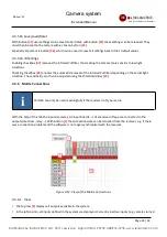
Page 22: ...light situation The sensitivitiy can then be adjusted using the threshold slider 29 4 3 6 Matrix Connections i This tab can only be used meaningfully if the receiver is of type matrix With the help o...

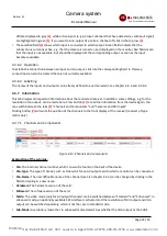
Page 23: ...n of an output can be made here Press button 1 to read the information from the device again You can switch between the tabs 2 Channels and Components and Cameras and DVI Inputs Clicking button 3 will...

Page 24: ...camera Here you can see which camera type SD HD Mini etc is physically connected to the corresponding channel ID This is the ID of the camera physically connected to this channel or the ID of the AV i...

Page 25: ...on the font size with the origin in the upper left corner of the screen Column 4 defines the foreground color font color of the text column 5 the background color Enter the text to be displayed in th...

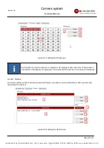
Page 26: ...d With the selection list 2 the group to be edited is selected first If the group already exists all camera IDs belonging to the group are marked in table 1 Here you can add or deselect any cameras as...

Page 27: ...the camera is selected for a third group the group can be created but the camera is not added to the group 4 3 8 5 Macros For simple overlays without the aid of external software two macros can be de...

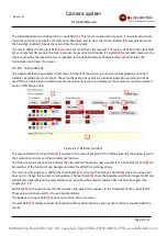
Page 28: ...isplayed these cameras must be selected on the OSD Groups tab Figure 4 19 OSD test functions The text entered in the input field 1 is written to the current position of the OSD by pressing the button...

Page 29: ...ceiver and remote control types can be defined via configuration files see chapter 4 4 3 and stored in the device using the functions shown here Button 1 sets the data in the receiver where it is imme...

Page 30: ...must be 255 255 255 255 In receivers of type Matrix slots can be equipped with relay cards to relay AV signals see chapter 2 3 to other receivers In this case the target systems max 3 must be created...

Page 31: ...meaningful names can be assigned to the individual serial interfaces This is done per line with the following syntax COMx Text where x stands for the number of the interface and text represents a use...

Page 32: ...ersions are separated in the line by a e g Col2 Mon 1 M 1 means that output 2 Col2 is displayed in the software as Mon 1 as well as on the colored display of the receiver where the texts Mon and 1 are...

Page 33: ...olon a command name a target address and a variable number of parameters Following rules apply Prefix and command name must be written in capital letters Command name target address and parameters mus...

Page 34: ...sition x y OSD CLR Clears transient text from screen Does not clear permanent text time and date see chapter 5 4 Table 5 1 Transient OSD commands 5 3 2 Description of Parameters 5 3 2 1 Address The ta...

Page 35: ...y on the OSD depends on the output screen resolution and the font size Table 5 3 shows the most common combinations For other combinations you use the character widths and heights listed table 5 4 for...

Page 36: ...mera IDs 1 8 Using OSD TXT and OSD TXTABS the time or date can be displayed in a user defined format A command with the new value must be sent for each update 5 4 Permanent OSD Commands Permanent OSD...

Page 37: ...D PDATE Sets font size position and colours for the displaying the current date A valid date must be set using MX DATE OSD PSTORE Stores permanent OSD configuration so that it is restored after restar...

Page 38: ...nel 19 Matrix v035 00 Tabletop Singlechannel v045 05 2 Tabletop Multichannel 19 v035 00_uC 07 Matrix v045 00 Tabletop Singlechannel v045 05 Table 5 9 Permanent OSD commands supported by receiver type...

Page 39: ...attery and no real time clock send MX TIME and MX DATE on each start of the receiver After that send MX TIME cyclically depending on the required accuracy Option real time clock provides an accuracy o...

Page 40: ...ckground colour 6 and text BAT OK for battery status OK 5 5 Obsolete OSD Commands Deprecated Obsolete OSD commands are still supported to provide backward compatibility It is not recommended to use th...

Page 41: ...the video source to the AV input card see chapter 2 2 2 3 Relay card Target receiver does not display the relayed AV signal at the output Relay card at the source receiver is not switched to the corre...

Page 42: ...ch the camera to an output and try again Camera Control Software Input not available Camera off or incorrectly configured Battery empty See base manual Incorrect ID set on camera Camera incorrectly wi...

Reviews: