Camera system
messtechnik
EMC Test and Measuring Systems
mk
Extended Manual
off) are displayed in gray
[4]
, while active inputs (e.g. AV input channels that have detected a valid input signal)
are highlighted in green
[5]
. If you want to turn output of a certain channel off, click in the top row
[3]
.
•
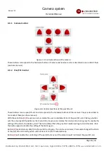
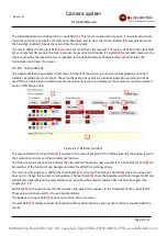
The selection field
[6]
shows which input is connected to which output. Green fields indicate that the
connection is currently active, e.g. that the camera is turned on and displayed on the monitor. Red fields mean
that the input is not available, but should be displayed at the corresponding output as soon as the input
becomes available.
4.3.6.2 Operation
To establish a connection between an input and an output, click into the corresponding field. In this way,
connections can also be created that are not currently available.
4.3.6.3 Labelling
The names of the inputs and outputs can be freely defined to a certain extent, see chapter 4.4.3 and 4.3.9.2.
4.3.7 Information
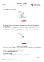
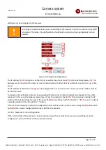
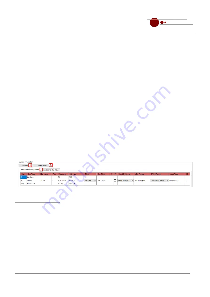
This tab displays all important information about the connected receiver. In addition, some settings, e.g. for the
resolution of an output, can be made here. Press button
[1]
to read the information from the device again. You
can switch between the tabs
[2]
"Channels and Components" and "Cameras and DVI Inputs".
Clicking button
[3]
will write the position of the channels to the front display of the receiver (receiver of type
matrix only)
4.3.7.1 Channels and Components
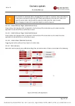
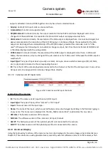
Figure 4-13: Channels and components
Explanation of the columns:
•
Chn:
the internal channel number, which can also be found on the back of the device.
•
Chn-Type:
The type of channel, such as Video-Out for an AV output card to which a monitor can be connected.
•
Chn-Name:
The user definable name of the channel (see also chapter 4.4.3) can be changed by clicking in the
field and typing in a new name.
•
Hardware:
The hardware version of the card.
•
Software:
The software version of the card.
•
Mode:
The video mode (only for AV output channels) can be switched between "Standard" and "Enhanced". In
enhanced mode, an optionally available SDI interface is activated and the resolutions of DVI output and VGA
output can be switched separately, which is not the case in standard mode.
•
Sub-Mode:
A secondary mode that, in enhanced mode, determines whether the VGA output or the CVBS
Page 24 / 43
Distributed by: Reliant EMC LLC, 3311 Lewis Ave, Signal Hill CA 90755, 4089165750, www.reliantemc.com


