Camera system
messtechnik
EMC Test and Measuring Systems
mk
Extended Manual
A-Out
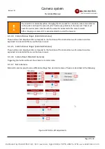
Figure 2-2: Connectors of the audio output card
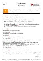
When option SDI video output is selected, the card does not have a CVBS cinch connector. Instead, CVBS and
audio are available through a combined audio/video (TRRS) female connector, see figure 2-3. To activate the SDI
video output, the mode of the card must be changed to „Enhanced“, see chapter 4.3.7.1.
VGA-/DVI-Out
SDI-Out
AV-Out
optical I/O
Figure 2-3: Connectors of output cards with option SDI
2.2.2 Audio/Video Input Card
The AV-input card is used to feed audio and video signals into the receiver.
It is only available for receiver type matrix.
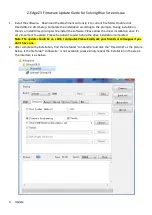
VGA Input DVI
Audio-In CVBS-In
U
p
D
ow
n
Figure 2-4: Connectors and operating controls of the AV-input card
2.2.2.1 Selection of the Video Input
The AV-input channel contains two physical connectors (DVI and Cinch) for the video input. You can connect an
analogue CVBS-signal to the Cinch connector. To the DVI-connector you can connect either DVI-signals, HDMI-
signals, or VGA-signals using an appropriate adapter.
Select the video input to be used in the receiver as follows:
•
Switch/LEDs at the AV-input channel card
Switch and LEDs are optional.
Using the toggle switch you can select between VGA, DVI/HDMI and CVBS. Move
the switch into the desired direction as indicated on the AV-input channel card. The LEDs indicate, which input
is selected.
After using the switch, it takes about 5 seconds before the video input can be changed again. This is
shown by the blinking of the LED.
Page 6 / 43
Distributed by: Reliant EMC LLC, 3311 Lewis Ave, Signal Hill CA 90755, 4089165750, www.reliantemc.com


