Please record the following information for your records:
Serial Number:
Date of Purchase:
Dealer Name:
Dealer Address:
City/State/Zip:
Country:
Invoice Number:
Bass Management Controller
TABLE OF CONTENTS
1.
SAFETY PRECAUTIONS..........................................................................................................3
2.
M&K’S DESIGN PHILOSOPHY...................................................................................................4
THE LOGIC OF BASS MANAGEMENT, OBSERVATIONS BY KEN KREISEL..........................4
4.
INTRODUCTION.........................................................................................................................5
INPUT AND OUTPUT CONNECTOR WIRING...............................................................7
GENERAL CONNECTION GUIDELINES........................................................................7
5.
GROUNDING......................................................................................................................7
6.
CONNECTING FOR STEREO......................................................................................................8
7.
CONNECTING FOR DOLBY DIGITAL.........................................................................................9
8.
CONNECTING FOR DTS...........................................................................................................10
9.
CALIBRATING YOUR M&K PROFESSIONAL SYSTEM...........................................................11
THE M&K PROFESSIONAL TEST DISC......................................................................11
10.
SPEAKER PLACEMENT.....................................................................................................12
ITU-R BS.775.1 RECOMMENDATION...........................................................................12
11.
GENERAL GUIDELINES FOR SPEAKER PLACEMENT..........................................................12
12.
SUBWOOFER PLACEMENT.....................................................................................................13
13.
SPEAKER CALIBRATION....................................................................................................14
14.
SUBWOOFER CALIBRATION...................................................................................................14
15.
SPECIFICATIONS.....................................................................................................................15
DIAGRAMS
FIGURE 1
FRONT PANEL.................................................................................................................6
FIGURE 2
REAR PANEL...................................................................................................................6
FIGURE 3
GROUNDING..................................................................................................................7
FIGURE 4
STEREO CONNECTIONS................................................................................................8
FIGURE 5
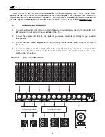
DOLBY DIGITAL 5.1 CONNECTIONS.............................................................................9
FIGURE 6
DTS 5.1 CONNECTIONS...............................................................................................10
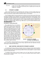
FIGURE 7
ITU-R BS.775-1 SPEAKER PLACEMENT......................................................................12
FIGURE 8
SPEAKER CABINET ORIENTATION.............................................................................13
2


