1.
SAFETY INSTRUCTIONS
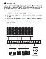
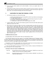
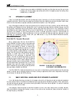
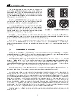
1. READ INSTRUCTIONS - All safety and operating instructions should be read before this product is operated.
2. RETAIN INSTRUCTIONS - The safety and operating instructions should be retained for future reference.
3. HEED WARNINGS - All warnings on this product and in the operating instructions should be adhered to.
4. FOLLOW INSTRUCTIONS - All operating and use instructions should be followed.
5. ATTACHMENTS - Do not use attachments not recommended by the product manufacturer as they may cause hazards.
6. WATER AND MOISTURE - Do not use this product near water - for example, near a bathtub, washbowl, kitchen sink,
or laundry tub; in a wet basement; or near a swimming pool; and the like.
7. ACCESSORIES - Do not place this product on an unstable cart, stand, tripod, bracket, or table. The product may fall,
causing serious injury to a child or adult, and serious damage to the product. Use only with accessories recommended
by the manufacturer, or sold with the product. Any mounting of the product should follow the manufacturer's instructions
and should use a mounting accessory recommended by the manufacturer.
8. POWER SOURCE - This product should be operated only from the type of power source indicated on the marking label. If
you are unsure of the type of power supply to your home, consult your product dealer or local power company.
9. OVERLOADING - Do not overload wall outlets or extension cords as this can result in a risk of fire or electric shock.
10. LIQUID ENTRY - Never spill any liquid of any kind on the product.
11. SERVICING - Do not attempt to service this product yourself. Opening or removing covers, including any over bottom or
side speaker drivers, may expose you to dangerous voltage or other hazards. Refer all service to qualified service
personnel.
12. DAMAGE REQUIRING SERVICE - Unplug this product from the wall outlet and refer servicing to qualified personnel under
the following conditions:
•When the power-supply cord or plug is damaged.
•If liquid has been spilled, or objects have fallen into this product.
•If the product does not operate normally by following the operating instructions. Adjust only controls that are covered by the
operating instructions as an improper adjustment of other controls may result in damage and will often require extensive
work by a qualified technician to restore the product to its normal operation.
•If the product has been dropped or damaged in any way.
•When the product exhibits a distinct change in performance - this indicates a need for service.
13. REPLACEMENT PARTS - When replacement parts are required be sure the service technician has used replacement part
specified by the manufacturer or have the same characteristics as the original part. Unauthorized substitutions may result in
risk of fire, electric shock, or other hazard.
14. SAFETY CHECK - Upon completion of any service or repairs to this product, ask the service technician to perform safety
checks to determine that the product is in proper operating condition.
15. HEAT - This product should be situated away from heat sources such as radiators, heat registers, stoves, or other products
(including amplifiers) that produce heat.
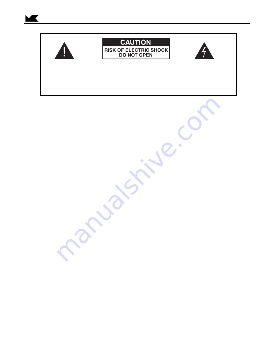
The exclamation point within an
equilateral triangle is intended to
alert the user of the presence of
important operating and mainte-
nance (servicing) instructions in
the literature accompanying the
appliance.
CAUTION:
TO PREVENT THE RISK OF ELECTRIC SHOCK,
DO NOT REMOVE COVER (OR BACK). NO USER-
SERVICEABLE PARTS INSIDE. REFER SERVIC-
ING TO QUALIFIED SERVICE PERSONNEL.
The lightning flash with arrowhead,
within an equilateral triangle, is
intended to alert the user of the
presence of uninsulated “dangerous
voltage” within the product's enclo-
sure that may be of sufficient magni-
tude to constitute a risk of electric
shock to persons.
Bass Management Controller
3


