background image

                                                                                                                             page 15

powered subwoofers

Subwoofer is the source of the hum.  If you hear no hum or less hum, the problem is
probably coming from another component.

Hum can also be caused by AC ground loops.  If the Subwoofer is plugged into a
separate AC outlet, try plugging it into the same outlet used for your amplifier or
receiver, or reverse the polarity of its AC plug.  If these suggestions do not solve
your problems, contact your dealer or M&K.

7.

If there is an unusual sound coming from the Subwoofer with no music playing:

Try removing the input cables as described in Step 5 above.  If the noise disappears, it is coming
from another component.  If it does not go away, contact your M&K dealer or the factory.

IF YOU NEED TO REPLACE THE EXTERNAL FUSE:

Disconnect supply cord before changing fuse.  Replace fuse only with same type.

Remove the fuse cap.  If the fuse cap has an arrow printed on it, push the cap in and turn it
counterclockwise.  If the fuse cap has a slot in it, use a flat head screwdriver to turn it counterclockwise.
Look carefully at the fuse.  If the wire filament inside the glass is broken, replace the fuse ONLY with
one of the identical size and value.  Using a fuse of a larger value will void your warranty AND MAY
CREATE A FIRE HAZARD
.  Plug the Subwoofer back in.  If it does not work, unplug it immediately,
and contact your dealer or M&K for service.

REPLACEMENT FUSE VALUES (units with U.S. standard fuses)

Replace only with same type 3AG-250 VAC SLO-BLO 1 1/4" x 1/4" fuse.

MODEL

110 v

220 v

MODEL

110 v

220 v

MX-2000

6 amp

3 amp

MX-300

6 amp

3 amp

MX-200

4 amp

2 amp

MX-700

5 amp

2.5 amp

MX-145

2.5 amp

1.25 amp

MX-125 Mk II

4 amp

2 amp

MX-100

4 amp

2 amp

MX-105 / Mk II

2.5 amp

1.25 amp

MX-90

2 amp

1 amp

MX-80

1.25 amp

.75 amp

MX-70/MX-70B

2 amp

1 amp

V-100

4 amp

2 amp

V-125

2 amp

1 amp

V-90

1.25 amp

.75 amp

V-75/V-75 Mk II 1.25 amp

.75 amp

V-3B

1.25 amp

.75 amp

VX-4

1 amp

.75 amp

VX-7B/VX-7 Mk II

1 amp

.75 amp

VX-100

2 amp

1 amp

REPLACEMENT FUSE VALUES (units with IEC 127-2/III standard fuses)

Replace only with same type IEC 127-2/III 5 X 20 mm timelag "T" fuse.

MODEL

220 v

MODEL

220 v

MODEL

220 v

MX-2000

2.5 A

MX-300

2.5 A

MX-200

1.6 A

MX-145

1 A

MX-125

1.6 A

MX-100

1.6 A

MX-105 / Mk II

1 A

MX-90

800 ma

MX-80

630 ma

MX-70/70B

800 ma

V-100

1.6 A

V-125

800 ma

V-90

630 ma

V-75/V-75 Mk II 630 ma

V-3B

630 ma

VX-4

630 ma

VX-7/7B/Mk II

630 ma

VX-100

800ma

Summary of Contents for M&K V-125

Page 1: ...ferson Boulevard Culver City CA 90232 USA 310 204 2854 FAX 310 202 8782 http www mksound com 1998 Miller Kreisel Sound Corp operation manual MX 700 MX 200 MX 125 Mk II MX 105 Mk II MX 70B VX 100 V 125...

Page 2: ...ASING TEST 10 6 USE OF THE LOW PASS FILTER CONTROL 11 7 USE OF THE BYPASS SWITCH 11 8 USING MULTIPLE SUBWOOFERS 11 9 HOMETHEATREUSAGE 12 CONNECTING TO A SURROUND SOUND RECEIVER OR PROCESSOR 12 10 SPEC...

Page 3: ...ug this product from the wall outlet and refer servicing to qualified personnel under the following conditions a When the power supply cord or plug is damaged b If liquid has been spilled or objects h...

Page 4: ...st structural strength If the corners are roughly equal in construction use the corner nearest the listening position If the listening position is in the front half of the room place the subwoofer in...

Page 5: ...ubwoofer truly non directional Except for the MX 700 VX 100 and V 125 M K Subwoofers are not magnetically shielded Leave 2 3 feet of clearance around any television set Shielding avoids magnetization...

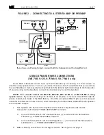
Page 6: ...jacks on the Subwoofer s backplate See Figure 1 It is not necessary to use both input jacks on the subwoofer Figure 1 below shows the connection method for a surround processor or receiver Figure 2 sh...

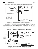
Page 7: ...el See Figure 3 on page 8 If you have one Preamp Output connect both the Subwoofer and the Amplifier to it 100 PHASE 1 0 3 9 1 J e f f e r s o n B l v d C u l v e r C i t y C A 9 0 2 3 2 3 1 0 2 0 4 2...

Page 8: ...C A 9 0 2 3 2 3 1 0 2 0 4 2 8 5 4 M I L L E R K R E I S E L S O U N D C O R P O R A T I O N RIGHT INPUT BASS LEVEL LOW PASS FILTER Hz FROM AMPLIFIER MAX 50 75 60 125 Made in U S A T 4 AMP 120 VAC 50 6...

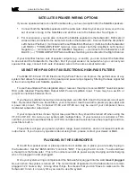
Page 9: ...the amp or receiver MUST have back panel RCA jacks labelled Preamp Main Output AND Power Amp Main Input There may be a switch or jumper connections between them If you have a multichannel surround so...

Page 10: ...liar CD LP or tape with steady consistent bass Listen carefully to the mid bass 70 100 Hz region the part of the spectrum where electric or string basses and drums are found Then move the PHASE switch...

Page 11: ...llite speakers and the Subwoofer When you hear a smooth sound overall well balanced between the deep bass and the rest of the audible spectrum the control is set properly 7 USE OF THE BYPASS SWITCH MX...

Page 12: ...nel WIDE NORMAL switch MUST be set to the NORMAL mode If the switch is set to the WIDE mode the bass content of the Center channel will not be fed to the Subwoofer and a significant amount of the bass...

Page 13: ...ver comes from the opening in the front baffle The solid grille cover insures that this is the case MX 700 VX 100 The MX 700 and VX 100 s pressure loaded design allows for maximum coupling to a room b...

Page 14: ...are in phase Reverse the and the connections for ONE CHANNEL ONLY at the FROM AMPLIFIER terminals If the problem remains put the cables back as they were Then perform the test in Step 4 4 If the midba...

Page 15: ...ss is broken replace the fuse ONLY with one of the identical size and value Using a fuse of a larger value will void your warranty AND MAY CREATE A FIRE HAZARD Plug the Subwoofer back in If it does no...

Page 16: ...ave a message and we will return your call DO NOT RETURN YOUR SPEAKERS TO THE FACTORY FOR SERVICE WITHOUT OBTAINING PRIOR AUTHORIZATION All M K powered subwoofers carry a three year limited parts and...

Page 17: ...tem setup is the Laserdisc or DVD called Video Essentials If you don t have one you can order it by calling 1 800 USA DISC 872 3472 Here are the instructions for speaker setup 1 Locate the front speak...

Page 18: ...maging 6 If you have a Dolby Digital AC 3 5 1 channel processor receiver follow these instruc tions If you have a Pro Logic processor receiver go to item 7 below SPECIAL NOTE Always check the processo...

Page 19: ...ing levels NOTE If you using identical speakers anywhere in your system e g S 150THX speakers for the left center and right channels all of those channels should be set to the same level If your meter...

Reviews: