satellite speakers
page 12
to the LOW EFFICIENCY position. Relative to NORMAL, the LOW EFFICIENCY position has an warmer, mellower
mid-bass sound with a more distant perspective.
When you are locating the speaker directly on a surface such as a wall, floor or ceiling, you may find that HIGH
EFFICIENCY position gives the best response. This is because this position best matches the increase in midbass
response that occurs when a speaker is directly against a room surface. (This is referred to as 2
π
space, as opposed
to a speaker located out in a room, which is known as 4
π
space. The HIGH EFFICIENCY position should be tried first
for 2
π
conditions, and the NORMAL position should be tried first for 4
π
conditions).
If you are optimizing your system's response with a third-octave equalizer and calibrating the equalizer by using
a third-octave analyzer, use the HIGH EFFICIENCY position. It will give you maximize output and dynamic range, while
placing the least demand on your power amplifier.
The LOW EFFICIENCY position trades efficiency and output for a warmer, mellower sound. If your room has a
lot of reflective surfaces or you have an otherwise bright-sounding system, try this position. LOW EFFICIENCY is
sometimes referred to as the "English sound." Some listeners will prefer it to the NORMAL position in any room, so
we suggest that you at least make a comparison.
All positions have the same power handling capacity, but their sensitivity varies (from highest to lowest) as follows:
HIGH EFFICIENCY, NORMAL, and LOW EFFICIENCY. Note that as you switch to a higher efficiency, the subwoofer
level needs to be set higher. Conversely, when you switch to a lower efficiency, the subwoofer level should be set lower.
S-1C TREBLE CONTOUR SWITCH
The TREBLE CONTOUR switch gives you control of the upper midrange and treble frequencies when set to the
HIGH or LOW positions. These carefully shaped contours control brightness to account for room conditions, other
electronics, or the source material. It is more sophisticated than a simple tweeter level control.
The LOW position produces an attenuation of high frequencies, while the HIGH position provides a slight rising
characteristic of the high frequencies when measured on-axis. The NORMAL position provides a flat on-axis response
to beyond 20 KHz.
This control is useful not only to match your room environment and speaker location, but also because audio and
audio/video program material varies widely in terms of high frequency level and distortion. For example, many
recordings and film soundtracks have artificially boosted, excessive high frequencies that will be clearly reproduced
by the exacting and extended high frequency reproduction of your M&K Satellites, and LOW TWEETER will help these
recordings. Many absorptive, "dead" rooms seem to soak up high frequency energy and excitement, and in these
cases, HIGH TWEETER should be used.
Don't hesitate to set this switch to HIGH or LOW for fear of the sound not being "flat". Few recordings are actually
"flat", due to equalization in the recording process, and artificial alteration of high frequencies is common.
S-1C DIRECTIVITY CONTROL SWITCH
An important design element of the S-1C is its specially controlled vertical radiation pattern. This improves stereo
imaging by reducing the amount of sound that it radiates above and below the speaker. When this sound reflects from
a recording console or the room's floor and ceiling, it then arrives at your ear later than the direct signal (because of
the time delay of the reflections). The delay of these reflected signals “blurs” the sound, producing a poor stereo image.
In the S-1C, this performance enhancement is achieved through its vertical tweeter array and matching cabinet
foam treatment. To further improve on this, a brand-new feature in the S-1C is its DIRECTIVITY CONTROL switch.
This unique three-position switch allows you to vary the amount of control applied to the high frequency radiation pattern.
In the WIDE position, the greatest amount of high frequency sound is allowed to radiate toward the floor and ceiling.
The NORMAL position produces the sharpest forward imaging through maximum attenuation of the high frequency
energy radiated toward the floor and ceiling, and the MID position falls in-between these two extremes.
The optimum setting for your system will depend on your room, your personal preference, and even the source
material that you are listening to. You may find that you prefer one setting for two-channel stereo and a different one
for multi-channel (four or five channel surround) listening. If you do most of your listening seated in one location, the
NORMAL position may be your preference. If you spend a great deal of time listening to the system standing, as well
as sitting, the WIDE position may work best. This is ultimately a subjective judgment, so we recommend that you
experiment to find the position that works best for your purposes.
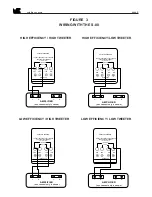
BI - WIRING THE S-1C
Bi-wiring is an advanced audiophile technique that can improve the sound quality that you hear from your S-1C
Satellites. It requires two sets of speaker wires running from the amplifier to EACH speaker, so it can be expensive.


