SS-150THX satellite speaker
page 5
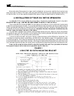
If you are mounting the bracket to a wall stud, drill two 3/32" holes per bracket. Remember that the wallboard
material is 1/2" or 5/8" inches thick, and you will drill through this before meeting the stud. If you are mounting the
bracket to drywall with the plastic anchors, drill two 1/4" pilot holes per bracket. Once all holes have been drilled,
remove the template from the wall. Press the plastic wall anchors into the 1/4" pilot holes until they are flush with the
wall. Tap them gently into place if necessary. Tape the four corners of the template sheet to the wall in the location
you have selected, using a carpenter's level to make sure the line marked "LEVEL TEMPLATE TO THIS LINE" is level.
The template sheet has locations marked for two mounting holes for the bracket needed to hang the SS-150
THX
s.
Once you are absolutely certain that you have the correct location, you are ready to drill the pilot holes. Go ahead
and drill right through the paper template into the wall. Re-check your measurements (especially making sure the
holes are level) at least once before drilling. Follow the instructions on the template.
WARNING: IT IS POSSIBLE THAT ELECTRICAL WIRING MAY BE LOCATED BEHIND THE WALL AT THE
LOCATION THAT YOU HAVE SELECTED. BE EXTREMELY CAREFUL ANY TIME YOU DRILL INTO A WALL.
Once the holes are drilled, place one bracket against the wall, making sure that the "tongue" (the portion that
engages the bracket on the speaker) is facing away from the wall and pointing up. Using the two #6 - 1 3/4" wood
screws provided, fasten this bracket to the wall. BE VERY CAREFUL. DO NOT FORCE THE PLASTIC ANCHORS
THROUGH THE WALL OR OVERTIGHTEN THE SCREWS. Install the second bracket in the same fashion.
That's it! All that is left for you to do is attach the speaker wire to the input terminals (Section 5, below), and,
from the top, gently slide the speaker into place against the wall. Do the same for the other channel.
5. SS-150THX SPEAKER HOOK-UP
LEFT SURROUND SPEAKER / RIGHT SURROUND SPEAKER
Your SS-150
THX
s come in left and right channel versions. Externally, both speakers may appear to be identical,
but in fact it is critical that the correct speaker be used in each channel.
On the back of the speaker is a label with an arrow printed with the nomenclature "Point Arrow Towards Screen."
To properly install the SS-150
THX
s, make sure that the arrow printed on each speaker is oriented properly. When the
speakers are on the side walls, the arrows should be pointed towards the television screen. When the speakers are
mounted on the back wall, the arrows should point to the nearest corner. The arrows will not be visible once the speaker
is installed.
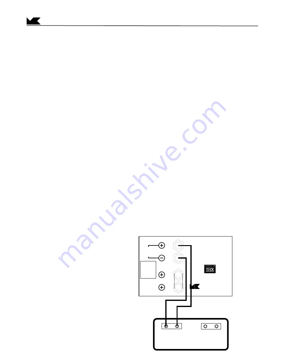
WIRING THE SS-150
THX
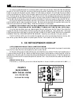
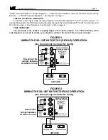
The Positive ( + ) lead from your surround channel amplifier or receiver should be connected to the RED ( + )
FIGURE 2
BASIC WIRING
WITH THE SS-150THX
(one channel only
is shown for clarity)
MADE IN USA
SS-150
THX
TRIPOLE
SURROUND SPEAKER
MILLER & KREISEL
SOUND CORPORATION
10391 Jefferson Boulevard., Culver City, CA 90232
Voice (310) 204-2854 Fax (310) 202-8782
Manufactured under license from Lucasfilm Ltd.
U.S. Patent Nos. 5,043,970; 5,109,416; 5,189,703;
and 5,222,059. Foreign patents pending. Lucasfilm
and THX are registered trademarks of Lucasfilm Ltd.
INPUT
4 ohms
FOR TRIPOLE
OPERATION:
install jumper
between
terminals
3 and 4
DO NOT CONNECT YOUR
AMPLIFIER TO TWO RED
TERMINALS.
1
3
2
4
FOR THX
(DIPOLE)
OPERATION:
remove jumper
between
terminals
3 and 4
Connect your
amplifier to
terminals
1 and 2.
For remote control operation,
see your owner's manual.
AMPLIFIER
RIGHT SURROUND
+
_
+
_
LEFT SURROUND


