background image

operation manual

CS-150 Tripole

®

CS-35 Tripole

®

CS-29 Tripole

®

CS-22 Tripole

®

Miller & Kreisel Sound, Inc.
9351 Deering Avenue
Chatsworth, CA 91311-5858 USA
(818) 701-7010 fax (818) 701-0369
www.mksound.com

©2002  Miller & Kreisel Sound, Inc.

tripole

®

column 

surround 

speaker

TM

Summary of Contents for Tripole CS-150

Page 1: ...ole CS 35 Tripole CS 29 Tripole CS 22 Tripole Miller Kreisel Sound Inc 9351 Deering Avenue Chatsworth CA 91311 5858 USA 818 701 7010 fax 818 701 0369 www mksound com 2002 Miller Kreisel Sound Inc tripole column surround speaker TM ...

Page 2: ...E 2 WIRING THE SURROUND SPEAKER CS 150 ONLY 4 FIGURE 3 DIPOLE OPERATION CS 150 ONLY 5 FIGURE 4 TRIPOLE OPERATION CS 150 ONLY 5 FIGURE 5 LOCATING THE SPEAKER NEXT TO THE LISTENER 6 FIGURE 6 LOCATING THE SPEAKER BEHIND THE LISTENER 6 FIGURE 7 SPEAKER LOCATION WITH ONE ROW OF LISTENERS 6 FIGURE 8 SPEAKER LOCATION WITH TWO ROWS OF LISTENERS 6 FIGURE 9 USING 4 SURROUND SPEAKERS 7 FIGURE 10 USING A SING...

Page 3: ...open or behind a couch chair or other furniture And with its baseboard mount you can permanently secure it to the base of any wall without sacrificing any floor space Using exceptionally high quality European drivers the Column Surrounds produce a brilliant sound quality with an incredibly large sound evoking the quality of M K professional monitors You ll hear the world class sound quality that h...

Page 4: ...nnel speaker If you are using multiple surround speakers or have a 6 1 channel system make sure that all surround speakers are being used in the proper right or left channel WIRING THE SURROUND SPEAKERS The Positive lead from your amplifier or receiver should be connected to the RED INPUT terminal and the Negative lead from your amplifier or receiver should be connected to the BLACK INPUT terminal...

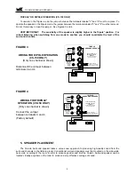
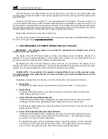
Page 5: ... MILLER KREISEL SOUND CORPORATION 9351 Deering Avenue Chatsworth CA 91311 818 701 7010 fax 818 701 0369 www mksound com INPUT 4 ohms FOR TRIPOLE OPERATION install jumper between terminals 3 and 4 DO NOT CONNECT YOUR AMPLIFIER TO TWO RED TERMINALS 1 3 2 4 FOR THX DIPOLE OPERATION remove jumper between terminals 3 and 4 Connect your amplifier to terminals 1 and 2 For remote control operation see you...

Page 6: ...speaker as well as up towards the ceiling It is not necessary to place the speakers against a wall They will provide excellent sound away from walls and can be more easily concealed from view when they are placed next to furni ture On its pedestal base a freestanding Column Surround can be located out in the open or behind a couch chair or other fur niture For example a CS 22 with a height of only...

Page 7: ...ly one set of surround channel outputs for each channel connect both left speakers to the left output and both right speakers to the right output If you have a single rear center surround channel then place the speaker directly behind the listener See Figure 10 As always please feel free to call the M K factory if you have any questions 6 COLUMN SURROUND ASSEMBLY OPTIONS You have two assembly opti...

Page 8: ... rear of the Column Surround see diagram Repeat these instructions to assemble the second stand MOUNTING THE COLUMN SURROUND TO THE BASEBOARD Here are the parts you need 2 each Column Surround Speakers 2 each Baseboard Mounting Brackets 8 each 6 32 x 1 Flat Head machine screw PN 20356 4 each 8 x 1 1 2 Flat Head wood screws chrome TOOLS REQUIRED Phillips screwdriver ASSEMBLY Remove the contents of ...

Page 9: ...o your listening environment or personal preference You make these adjustments by choosing which input terminals jumpers and if desired resistors are used to connect the speaker to the amplifier PLEASE NOTE The sensitivity of the speaker is slightly different in each of the surround modes For critical listening when switching from one mode to another you should re calibrate the level of the surrou...

Page 10: ...e switcher output connected to Terminal 4 should be turned off For the Tripole mode the switch er output should be turned on Nothing else should be connected to the switch box especially your amplifier As another example you can also use a switcher to direct the signal from the amplifier to either Terminal 1 or Terminal 3 to switch between some of the custom modes described above See Figure 5 CAUT...

Page 11: ...aracter described above When tone controls or equalizers are used to boost frequencies the problem occurs much more rapidly Even a small boost of low or high frequencies can easily double the power requirement and lead to amplifier clipping at moderate levels Therefore you should use your tone controls judiciously avoiding extreme boosts of the bass and treble controls especially when you are list...

Page 12: ...COMMENDED POWER 25 watts RMS to 200 watts RMS MAXIMUM POWER 200 watts RMS unclipped peaks FREQUENCY RESPONSE 70 23 kHz 3dB CABINET DIMENSIONS 34 5 x 8 9 x 4 2 HWD BASE DIMENSIONS 0 75 x 10 75 x 10 HWD WEIGHT 24 lbs CS 29 IMPEDANCE 4 ohms MINIMUM POWER 10 watts RMS RECOMMENDED POWER 25 watts RMS to 200 watts RMS MAXIMUM POWER 200 watts RMS unclipped peaks FREQUENCY RESPONSE 70 23 kHz 3dB CABINET DI...

Reviews: