background image

SAFETY 


1

Nur Hauptdokument


EN 
 

§

1 Safety 

§1.1 Signal Explanation  


—

  The  above  signals  mean  warning!  Notice!  Running  parts  and  getting  an 

electric shock or thermal parts will take damage for your body or others. The 

corresponding notices are as follows. It is quite a safe operation after taking 

several necessary protection measures.   


§1.2 Arc Welding Damage 

—

 The following signals and word explanations are to some damages for your 

body or others happening on the welding operation. While seeing these, please 

remind of yourself or others to be dangerous. 

—

 Only ones who are trained professionally can install, debug, operate, maintain 

and repair the equipment. 

—

  During  the  operation,  non-concerned  people  should  be  lift,  especially  for 

children. 

—

 After shut off the machine power, please maintain and examine the equipment 

according to §5 because of the DC voltage existing in the electrolytic capacitors. 

ELECTRIC SHOCK CAN KILL. 

—

 Never touch electrical parts. 

—

 Wear dry, hole-free gloves and clothes to insulate yourself. 

—

 Insulate yourself from work and ground using dry insulation. Make certain the 

insulation is large enough to cover your full area of physical contact with work 

and ground.   

—

 Take carefully when using the equipment in small place, falling-off and wet 

circumstance. 

Summary of Contents for Multi-GMAW 200S

Page 1: ...1 0003 0520 E V 2 0 22 IMPORTANT Read this Owner s Manual Completely before attempting to use this equipment Save this manual and keep it handy for quick reference Pay particular attention to the safety instructions we have provided for your protection Contact your distributor if you do not fully understand this manual ...

Page 2: ...n 11 11 Fehlerursachen Behebung 12 12 Prüfen und Warten 13 13 Schematischer Schaltplan 14 Copyright 2020 MK Trade GmbH Wies Österreich Die Inhalte dieser Bedienungsanleitung sind alleiniges Eigentum der Firma MK Trade GmbH Eine Weitergabe sowie Vervielfältigung dieses Dokuments Verwertung und Mitteilung seines Inhalts sind verboten soweit nicht ausdrücklich gestattet Zuwiderhandlungen verpflichten...

Page 3: ...alten auch keine Reste davon Gefahr entflammbarer Gase Die Anlage nicht in Betrieb nehmen wenn die Umgebungsluft explosiven Staub o Gase enthält Behälter bzw Rohre die sich im Über bzw Unterdruck befinden dürfen nicht geschweißt werden Explosions bzw Implosionsgefahr Beachten Sie eine erhöhte Brand bzw Explosionsgefahr Das Berühren stromführender Teile kann tödliche elektrische Schläge oder schwer...

Page 4: ...mindern Schweißen von Blei auch in Form von Überzügen verzinkten Teilen Kadmium Beryllium und andere Metalle die beim Schweißen giftige Dämpfe entwickeln ist nur mit Atemschutzmaske und gerät sowie Absaugung und Filterung der giftigen Gase und Dämpfe erlaubt Erhöhte Vorsicht gilt beim Schweißen von Behältern diese müssen zuvor entleeren und Fachgerecht gesäubert werden Warnung Entstehung von Rauch...

Page 5: ...en sie das Gerät vor jeder Benutzung Benutzen sie nur originale Ersatzartikel 8 Folgen sie den Betriebsregeln beim betätigen der Schalter und bei Justierungen 9 Tragen sie beim Schweißen Schutzkleidung Dies beinhaltet ein langärmeliges T Shirt Lederärmel Schutzschürze ohne Taschen lange schützende Hosen Arbeitsschuhe und Schutzbrille Wenn sie mit heißem Material arbeiten sollten sie Schutzhandschu...

Page 6: ...Schweißgerät ist mit CE gekennzeichnet und entspricht den gültigen Normen EMC 2014 30 EU LVD 2014 35 EU EN 60974 10 2014 A1 2015 EN60974 1 2012 Das Multi GMAW 200S Schweißgerät besitzt die modernste IGBT Technologien Es hat mehr Leistung und höhere Effektivität so dass es mit üblichen Transformator Schweißgeräten nicht vergleichbar ist Der Schweißstrom ist sehr stabil Das Schweißgerät hat hervorra...

Page 7: ...en Abbildung dargestellt Wenn das Schweißgerät überhitzt sendet der IGBT Überhitzungsschutz ein Signal an die Schweißgerät Steuereinheit zum Abschalten des Ausgangsschweißstroms und gleichzeitig leuchtet die Überhitzungs Kontrolllampe an der Frontplatte In diesem Fall sollte die Maschine 10 15 Minuten lang nicht schweißen um sich mit dem Lüfterlauf abzukühlen Bei erneutem Betrieb der Maschine soll...

Page 8: ...7 DE 6 Funktionsbezeichnung 1 Euro Zentral Anschluss 2 Ausgang MINUS 3 Ausgang PLUS 4 Ein Aus Schalter 5 Gas Eingang 6 Kabel 7 Drahtrollen Halter Bild 1 ...

Page 9: ...ard Polung für die meisten Schweißdrähte ist Euro Zentral Anschluss auf Plus Pol Bild 1 13 und Masse auf Minus Pol Bild 1 2 Die Vorschubrolle Bild 1 11 muss dem Drahtdurchmesser angepasst werden Hierfür kann diese umgedreht bzw durch eine passende Rolle mit passendem Durchmesser bzw Form ersetzt werden Hinweis Der Drahtanpressdruck muss je nach bedarf individuell Eingestellt werden dieser darf nic...

Page 10: ... Synergic Programm Manuell 7 Drahtvorschub 8 Display Spannungsanzeige V Induktion Drahtrückbrand Spot Zeit sek 9 Display Drahtvorschubgeschwindigkeit Ampere Anzeige HotStart Arc Force 10 Kontrollleuchte Netz 11 Alarm LED 12 Hot Start 13 Arc Force Alarm Leuchte Sollte das Gerät Überhitzen wird der Schweißvorgang Automatisch unterbrochen die Kontroll LED Leuchtet auf Gerät abkühlen lasen bis die LED...

Page 11: ...chte Schweißstrom durch drehen des Einstellknopfes Bild 2 4 eingestellt werden Mit dem Einstellknopf Bild 2 5 kann die Schweißspannung bei bedarf auf bis 4V bis 4V nachjustiert werden Weiters kann die Induktivität ind und Drahtrückbrand bub eingestellt werden Durch drücken des Einstellknopfes Bild 2 5 gelangen Sie zu den Parametern Spot Schweißen Aktivieren Sie hierzu die Spot Funktion dies wird s...

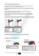
Page 12: ...er aufgedreht werden danach einen kurzen Kontakt mit dem Werkstück Masse herstellen und den Brenner wieder leicht anheben damit der Lichtbogen startet Zum Beenden des Schweißvorganges den Brenner schnell vom Werkstück abheben und danach das Gasventil am Brenner Schließen Gasnachlauf beachten zum Kühlen der Elektrode und Schweißbad ACHTUNG WIG Brenner und Elektrode stehen unter Spannung Richtiges S...

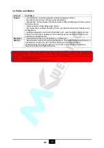
Page 13: ...sflasche aufdrehen bzw füllen lassen Gasdurchfluss zu gering Gasdruckregler einstellen Gaszuleitung geknickt Kontrolle Gasleitung Elektrode zündet nicht oder schlecht MMA Gerät auf WIG Betrieb eingeschalten Betriebsart auf MMA ändern Massekabel nicht angeschlossen oder schlechten Kontakt Massekabel am Werkstück anschließen bzw Kontakt verbessern Elektrodenhalter falsch gepolt Elektrodenhalter Pol ...

Page 14: ...an ein autorisiertes Fachpersonal Monatlich Das Gerät mit trockene Luft Ausblasen und Reinigen Jährlich Sicherheitstechnische Überprüfung EN 60974 4 Kalibration DIN EN IEC 60974 14 des Gerätes und Service Bei nicht Durchführung erlischt die Garantie Gewährleistung Das Service darf nur von einem vom Hersteller Autorisiertem Service Personal durchgeführt werden Jegliche Arbeiten im und am Gerät Ände...

Page 15: ...14 DE 13 Schematischer Schaltplan ...

Page 16: ...4 Operation 15 4 1 Layout for the front and rear panel 15 4 2 Welding operation 16 4 2 1 MIG mode operation 16 4 3 Welding parameters 18 4 4 Operation environment 18 4 5 Operation Notices 18 5 Maintenance Troubleshooting 19 5 1 Maintenance 19 5 2 Troubleshooting 20 5 3 Electrical schematic drawing 22 Copyright 2020 MK Trade GmbH Wies Austria The contents of these User Manual are the sole property ...

Page 17: ...s to be dangerous Only ones who are trained professionally can install debug operate maintain and repair the equipment During the operation non concerned people should be lift especially for children After shut off the machine power please maintain and examine the equipment according to 5 because of the DC voltage existing in the electrolytic capacitors ELECTRIC SHOCK CAN KILL Never touch electric...

Page 18: ... welding cable and welding machine in good safe operating condition Replace damaged insulation Never dip the electrode in water for cooling Never simultaneously touch electrically hot parts of electrode holders connected to two welders because voltage between the two can be the total of the open circuit voltage of both welders When working above the floor level use a safety belt to protect yoursel...

Page 19: ...d the consumables to be used including the material safety data sheet and follow your employer s safety practices ARC RAYS CAN BURN Use a shield with the proper filter and cover plates to protect your eyes from sparks and the rays of the arc when welding or observing open arc welding Use suitable clothing made from durable flame resistant material to protect your skin and that of your helpers from...

Page 20: ...and hot materials from welding can easily go through small cracks and openings to adjacent areas Avoid welding near hydraulic lines Have a fire extinguisher readily available Where compressed gases are to be used at the job site special precautions should be used to prevent hazardous situation When not welding make certain no part of the electrode circuit is touching the work or ground Accidental ...

Page 21: ...Use only compressed gas cylinders containing the correct shielding gas for the process used and properly operating regulators designed for the gas and pressure used All hoses fittings etc should be suitable for the application and maintained in good condition Always keep cylinders in an upright position securely chained to an undercarriage or fixed support Cylinders should be located Away from are...

Page 22: ...on we should minimize exposure to EMF as few as possible In order to minimize EMF we should use the following procedures Route the electrode and work cables together Secure them with tape when possible All cables should be put away and far from the operator Never coil the power cable around your body Make sure welding machine and power cable to be far away from the operator as far as possible acco...

Page 23: ...he above problems happens the alarm lamp on the front panel will be lighted and output current will be shut off automatically to protect itself and prolong the equipment using life MIG SERIES Features 1 Digital control system real time display the welding parameters 2 High performance multifunction power source MIG MAG 3 Waveform control stable welding arc 4 IGBT technology low power dissipation M...

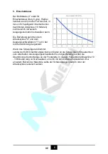
Page 24: ...nfinitely to meet with the requirements of welding craft 2 3 Volt Ampere Characteristic MIG SERIES welding machine has an excellent volt ampere characteristic whose graph is shown as the following figure The relation between the rated loading voltage U2 and welding current I2 is as follows U2 14 0 05I2 V 44 14 0 600 Io A Uo V Working point Volt ampere characteristic The relation between the rated ...

Page 25: ...OVERVIEW 9 Nur Hauptdokument EN 2 4 Principles of welding ...

Page 26: ...A 40 200 MIG 10 180 MMA 10 180A No load Voltage V 69 Duty cycle 40 30 200A 60 145A 100 110A 40 180A 60 160A 100 140A Welding Current Range A 40 200 MIG 10 180 MMA TIG Welding Voltage Range V 16 24 20 4 27 2 10 4 17 2 Diameter mm 0 6 0 8 0 9 1 0 Fe Ss Flux Cored Protection class IP23 Insulation class H Power factor 0 65 Efficiency 85 Dimensions mm 450 215 400 Weight Kg 12 Note The above parameters ...

Page 27: ...hen operating the machine again the welding output current or the duty cycle should be reduced 3 3 Equipment Connection 3 3 1 Polarity Connection MMA MMA DC Choosing the connection of DCEN or DCEP according to the different electrodes Please refer to the electrode manual 3 3 2Assembling the equipment MIG Operation Steps 1 Connect the power source input cable of welding machine with the output port...

Page 28: ...3 9 Handle locking ring 1 10 Cable fixing joint 15AK 1 11 Coaxial cable team 16mmq 3m 1 12 Cable thimble 12 16 25 MMQ 1 13 CO2 Euro rear thimble 1 14 Screw M4 6 UNI 6107 1 15 Torch locknut plastic screw thread 1 16 Euro main socket flexibility pin 1 17 Feeding pipe locknut 1 18 Insulating feed pipe 0 6 0 8 3m Blue 1 19 Spanner for the electric nozzle 1 3 4 3 The operation for the MIG GUN 标准化 工艺 批准...

Page 29: ... it to a new one according to the following instructions Open the mounting nut of the wire guide which exposes the end of the wire guide Straighten the welding gun s cable and withdraw the wire guide from the gun Push a new wire guide in to the gun Make sure that the wire guide enters all the way into the contact tip s adapter and that there is an O ring at the machine end of the guide Tighten the...

Page 30: ...nd fasten it with the pressure control lever Make sure that the wire runs in the feed roll groove Adjust the compression pressure with the pressure control lever no higher than to the middle of the scale If the pressure is too high it removes metal fragments from the wire surface and may damage the wire On the other hand if the pressure is too low the feed gear slips and the wire does not run smoo...

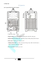
Page 31: ...polarity must connect the work piece 3 Output anode When MMAmode this polarity connect welding clamp or the work piece 4 On off switch Control the power supply on and off 5 Shield gas input joint To connect one head of the gas hose while the other head of which is connected to argon gas cylinder 6 Power source input To connect power source ...

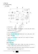
Page 32: ...T knob Set the welding current ARC FORCE HOT START 5 Welding Inductance Burnback voltage knob Set the welding volt Inductance Burnback 6 SYN Programs Select 7 Manual Wire Select 8 Voltage Inductance Burnback display Welding voltage display when machine is working Set voltage display when MIG mode before welding Unit V 9 Current ARC FORCE HOT START display Welding Current display when machine is wo...

Page 33: ...ent 2 Adjust the current knob the corresponding welding voltage is changed automatically 3 When the programmable welding voltage isn t the perfect for the operator the voltage can be changed tinily by adjusted the knob 4 You can use current setting knob to set the wire speed when the wire speed LED is on 5 If the operator adjust the wave control knob the arc characteristics can be controlled 4 2 2...

Page 34: ...ome angles above the floor level the maximum angle does not exceed 15 Protect the machine against heavy rain or in hot circumstance against direct sunshine The content of dust acid corrosive gas in the surrounding air or substance can not exceed normal standard Take care that there is sufficient ventilation during welding There is at least 30cm free distance between the machine and wall 4 5 Operat...

Page 35: ...ng machine are flexible and put correctly in place If the knob has not been put correctly in place please correct If you can t correct or fix the knob please replace immediately If the switch is not flexible or it can t be put correctly in place please replace immediately Please get in touch with maintenance service department if there are no accessories After turn on power watch listen to that wh...

Page 36: ...ord they should be regulated The actual current value can be measured by the adjusted plier type ampere meter Yearly examinati on Measure the insulating impedance among the main circuit PCB and case if it below 1MΩ insulation is thought to be damaged and need to change and need to change or strengthen insulation 5 2 Troubleshooting l Before arc welding machines are dispatched from the factory they...

Page 37: ...nge it Control circuit damaged Check the board Wire reel works The press wheel is loosen or weld wire skids Press it tightly again The wheel doesn t fit with the diameter of weld wire Change the wheel Wire reel damaged Change it Wire feed pipe is jammed Repair or change it Tip is jammed because of splash Repair or change it 5 No striking arc and no output voltage Output cable is connected mistaken...

Page 38: ...THANK YOU FOR USING OUR PRODUCTS 22 Nur Hauptdokument EN 5 3 Electrical schematic drawing ...

Page 39: ...erein und entsprechen den Sicherheitsanforderungen für Einrichtungen zum Lichtbogenschweißen gemäß den folgenden Produkt Normen Folgende harmonisierte Europäische Normen wurden angewandt EN 60 974 1 2012 Lichtbogenschweißeinrichtungen Teil 1 Schweißstromquellen EN 60 974 10 2014 A1 2015 Lichtbogenschweißeinrichtungen Teil 10 Elektromagnetische Verträglichkeit Anforderungen EMV Gemäß EG Richtlinie ...

Reviews: