background image

MKS MultiGas High-Speed Gas Sampling Cart 

Cart


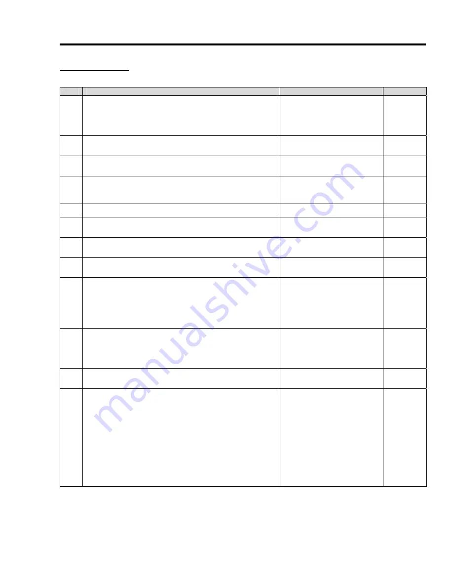
Daily


Use


STEP


ACTION


NOTES


COMPLETED


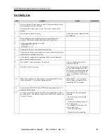
1.


The cart requires a 5-hour warm-up time. It is recommended to keep 
the system powered-on at all times. 

If starting with a cold system, see the “power up” section of this 
manual. 


2.


Turn off pumps when not in use. 

The pumps may be turned off when 
not sampling. 


3.


Periodically drain water condensation from the Backpressure 
reservoir.  Drain valve found at the bottom of the reservoir. 


4.


Verify temperature readings are stable: 
  HTD LINE 2: 191°C 
  HTD BOX: 191°C 


5.


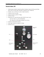
Verify that FM1 valve is in the full open position. 


6.


Verify that the back pressure regulator is fully-clockwise to decrease 
the backpressure through the system. 


7.


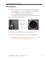
Verify that the sample line is connected.  Make sure the Swagelok 
quick connect is properly seated. 


8.


Turn the MV1 valve in the Span / N

2

 position. 

The valve handle moves left to 
right in a lower arc. 


9.


Turn MV2 to the N

2

 position.  


This is done to purge the MultiGas 
gas cell with Nitrogen gas so the 
daily checks can be performed and 
a new background reading can be 
taken.  See MultiGas SOP for daily 
checks. 


10.


When Daily checks are completed and a new background has been 
taken, turn the MV1 valve in the Sample position 

When the MV1 valve is moved 
from N

2

/Span to Sample all flow 

through the MV2 is stopped. 


11.


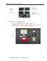
Verify that the HTD LINE 2 and HTD BOX temperatures are 191°C 
then turn ON the Pump. 


12.


Use the back pressure regulator to achieve the desired flow rate and 
gas cell pressure.  The pressure measured in the MG2000 should be at 
1.0 atm ± 0.05atm. 

If the pressure drops during the 
sampling: 

-  The filter may be coated with 
particulate 

-  Issue with the pumps, check to 
see if both pumps 
    are running.  Check front and 
rear cowling to see 
    if the fan is spinning. 
 
-  Restriction in the sample line 


Installation and Use Manual        2011 APRIL  2   Rev. 1.5


 32


Summary of Contents for 2480HS

Page 1: ...2480HS High Speed Sampling Cart Installation Use Manual PRELIMINARY...

Page 2: ...y any information storage or retrieval system except as may be expressly permitted in writing by MKS Instruments Inc MultiGas is a trademark of MKS Instruments Inc Wilmington MA National Instruments i...

Page 3: ...pport 9 System Overview 10 System Components 11 Operating Principle 13 Installation 14 Safety Notice 14 Facility Requirements 14 Cabinet System Dimensions 15 Installation Procedure 17 Required Equipme...

Page 4: ...5 Liter extended Dewar 34 Filling the 5 Liter Dewar 37 Access to the Electronics Box 38 Access to the Heated Box 38 Setting the thermal controllers 39 Troubleshooting 39 Replacing Pump Diaphragms and...

Page 5: ...tion to a procedure practice condition or the like which if not correctly performed or adhered to could result in injury to personnel Caution The CAUTION sign denotes a hazard to equipment It calls at...

Page 6: ...MKS MultiGas High Speed Gas Sampling Cart Symbols Found on the System The following table describes symbols that may be found on the unit Installation and Use Manual 2011 APRIL 2 Rev 1 5 6...

Page 7: ...ied service personnel only DO NOT OPERATE IN AN EXPLOSIVE ENVIRONMENT To avoid explosion do not operate this product in an explosive environment unless it has been specifically certified for such oper...

Page 8: ...e used to determine if the component could exceed the two person lift limitations and require a lift assist in order to position or remove it Refer to center of gravity drawings WARNING BURN HAZARD Al...

Page 9: ...ronmental requirements and how to install the system Operation describes how to use the instrument and explains all the functions and features Maintenance lists maintenance required to keep the instru...

Page 10: ...ntrollers for sample lines required to maintain the sample at 191 C as required for precision gas composition analysis quick connection for sample gas inlet line portable unit with standard electrical...

Page 11: ...gulator FM1Exhaust flow rotameter FM2 Flowmeter N2 or Span Inlet flow to system MV2 Valve to switch between N2 and Span Gas PRV SG Span Gas regulator MV1 Valve to Select allow Span N2 or Sample Gas to...

Page 12: ...ng Cart Inlet gas connector release Inlet gas quick disconnect port Liquid Nitrogen Dewer MultiGas Analyzer Computer Toxic vent Toxic Pressure Relief Span gas supply Nitrogen supply Installation and U...

Page 13: ...and span gas inlets and flow paths with regulators rotometers and manual flow selector valves are provided to provided span calibration and purge flows as required A low flow of nitrogen is maintaine...

Page 14: ...ch Use of appropriate power extensions cords are required for the power load and the installation work environment Nitrogen 1 slpm 0 20 psig high purity Gas Requirements Calibration Span Gas 1 slpm 0...

Page 15: ...ampling Cart Cabinet System Dimensions 71 inclusive of wheels 25 5 inclusive of wheel extensions 41 inclusive of wheel extensions Cart Approximate Dimensions With Drawers Closed Installation and Use M...

Page 16: ...s High Speed Gas Sampling Cart CART SYSTEM Service Space 113 74 Approximate Work Service Space Dimensions Note Service space can be shared with other equipment Installation and Use Manual 2011 APRIL 2...

Page 17: ...heck the shock and tilt indicators If an indicator has been triggered contact the shipping company immediately 2 The front door of the crate also acts as a ramp to safely remove the cart from the crat...

Page 18: ...o be shipped back to the factory it must be shipped in the original shipping crate or the warranty is void 6 Lock wheels when positioned at final destination 7 Inventory accessories Item PN Quantity S...

Page 19: ...inspect the filter If the filter is discolored or missing replace the filter element Replacing a filter element a Unscrew the Stainless screw end from the filter holder b Slide a new filter onto the f...

Page 20: ...is in the off position 2 Verify that all power cords are plugged into power strips 3 Check that all fuses and breakers are engaged 4 Push in all fuses and switch on all circuit breakers 6 Fuses and 2...

Page 21: ...iGas with the plumbing of the cart take care to align the connectors and snug each hand tight c Tighten the connections according to Swagelok instructions Note Take care not to cross thread the connec...

Page 22: ...he MultiGas accessory box with the Teflon line on the cart 5 Connect the female quick connect with the male quick connect found on the MultiGas Step 5 Install the Extended Dewar 1 Unpack the Dewar fro...

Page 23: ...ystem 3 Connect exhaust line to the port located on the rear lower panel labeled Toxic Vent to Facility exhaust Note Water may condense in the exhaust line Use a 7 8 inch diameter line less than 25 fe...

Page 24: ...MKS MultiGas High Speed Gas Sampling Cart Installation and Use Manual 2011 APRIL 2 Rev 1 5 24...

Page 25: ...up cart and stabilize temperature at 191 C 5 C Approximately 5 hours is required for initial startup stabilization 3 Turn the MV1 valve to the sample position 4 Turn on system pumps 5 Adjust back pre...

Page 26: ...e N2 position 4 Set the N2 pressure regulator to 20 psig 5 Set FM2 to 5 lpm 6 Nitrogen flow for instrument purge splits off from the same source a Remove the face cover from the MultiGas b Set purge f...

Page 27: ...sure to minimize the amount of potential cold spots in the sample train 2 Locate the opening at the rear of the heated box Quick connect release Heated line and quick connect seated View into the hea...

Page 28: ...ed connectors on the rear of the Electronics box Note The TC connector pictured below is wired for J type heated lines Note If there is no TC connector the cart is wired for K type lines Heated line p...

Page 29: ...ltiGas without the sampling cart the power cord plugs directly into an 110V wall socket instead of the cart 5 Power up the Computer This is done on the face plate of the computer Note The computer use...

Page 30: ...ilter optional external heated filter 8 Turn the MV1 valve in the sample position Note The valve handle moves left to right in a lower arc CAUTION If MV1 is not in the sample position no flow will go...

Page 31: ...n Only after the HTD LINE 2 and HTD BOX reaches 191 C 12 Make sure both pumps engaged o You should see both pump fans spinning front and back of cabinet 13 Adjust back pressure regulator to reach desi...

Page 32: ...e in the Span N2 position The valve handle moves left to right in a lower arc 9 Turn MV2 to the N2 position This is done to purge the MultiGas gas cell with Nitrogen gas so the daily checks can be per...

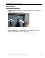
Page 33: ...from the housing 3 Visually inspect the filter If the filter is discolored or coated with particulate replace the filter element 4 Unscrew the Stainless screw end from the filter holder and slide a n...

Page 34: ...ed Dewar Mounting the 5 Liter Dewar Remove the fitting from the top of the optics box through the hole in the top cover Note Keep fitting for later uses It should be replaced if 5 L Dewar is removed f...

Page 35: ...opening of the top cover of the MultiGas CAUTION Take care not to cross thread the Dewar adaptor plate threads and the optics box threads Carefully screw the Dewar into the top of the optics box Rota...

Page 36: ...should only be used when transporting the Dewar while it contains LN2 Note DO NOT LEAVE THE PLUG IN DURING STANDARD OPERATION it could break off inside the Dewar Keeping it in place will cause the LN2...

Page 37: ...dewar Fill the Dewar carefully CAUTION Use appropriate safety equipment when handling liquid nitrogen When LN2 begins to come out of the VENT switch the valve back to the RUN position LN2 will now fl...

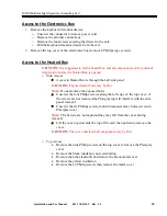
Page 38: ...ote Do not remove the exposed bolts Unscrew the four Philips screws along the left edge of the top cover if the screws are not removed the Plexiglas top will interfere with the side panel removal Unsc...

Page 39: ...or for leaking oil Heated Box will not reach 191 C Check the fuses Check the power Check strip heaters inside heated box Check that all five of the strip heaters are warming up Check that all ring con...

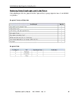
Page 40: ...antity Fork wrench or socket wrench 27 mm 1 Allen wrench 3 mm 1 Allen wrench 6 mm with torque indicator 1 Fork wrench 19 mm 1 Face spanner pin diameter 5 mm 1 Phillips screwdriver only for 11 or 26 ve...

Page 41: ...awing ID 1 Head screws 2 Disk springs 3 Head plate 4 Valve plates 5 O rings 6 Intermediate plate 7 Retainer plate 8 Diaphragm 9 Diaphragm support 10 Diaphragm spacers 11 Conrod extension 12 Carrier In...

Page 42: ...he carrier 12 with respect to the intermediate plate 6 with a continuous felt pen line 5 Remove intermediate plate 6 CAUTION Set down the intermediate plate carefully to avoid damaging its sealing edg...

Page 43: ...Lay new valve plates 4 in the valve seats of the intermediate plate 6 5 Fit the new O rings 5 in the intermediate plate 6 Dispose of the old diaphragm valve plates and O rings properly Mounting pump...

Page 44: ...MKS MultiGas High Speed Gas Sampling Cart Installation and Use Manual 2011 APRIL 2 Rev 1 5 44 Reference Drawings...

Reviews: