Chapter 2
22
Micro-Ion
®
Module Instruction Manual - 356007-GP
Grounding
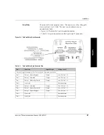
The module chassis must be properly grounded via the 15-pin subminiature
D connector and the chassis ground screw, as illustrated in Figure 2-7.
The module generates 180 Vdc during normal operation (Micro-Ion gauge
ON) and 250 Vdc during Micro-Ion gauge degas.
Figure 2-7
Ground Connections
WARNING
Improper grounding could cause product failure or
personal injury.
Follow ground network requirements for the facility.
•
Maintain all exposed conductors at earth ground.
•
Make sure the vacuum port to which the module is mounted
is properly grounded.
•
Connect the ground strap to the chassis ground screw on the
module end panel.
Chassis ground screw
Chassis ground is pin 15
Summary of Contents for 356 Micro-Ion Plus Series
Page 2: ......
Page 24: ...24 Micro Ion Module Instruction Manual 356007 GP...
Page 58: ...Chapter 3 58 Micro Ion Module Instruction Manual 356007 GP...
Page 74: ...Index 74 Micro Ion Module Instruction Manual 356007 GP...
Page 75: ......


