Operation
Micro-Ion
®
Module Instruction Manual - 356007-GP
27
In
stallation
O
per
a
tion
Maintenance
Before You
Begin
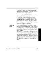
The amount of ion current for a given emission current and pressure
depends on the Micro-Ion gauge design. This gives rise to the definition of
ionization gauge sensitivity, frequently denoted by “S”:
When used with N
2
or air, the ionization gauge has a nominal sensitivity of
18/Torr (13.5/mbar, .135/pascal) at high emission current (4 mA)
or 20/Torr (15/mbar, .15/pascal) at low emission current (0.1 mA).
The module electronics for the gauge varies the heating current to the
filament to maintain a constant electron emission and measures the ion
current to the ion collectors. The pressure is then calculated from these
data.
Micro-Ion gauge degas is accomplished by increasing the emission current
to 15 mA and raising the grid bias to 250 Vdc, resulting in an increased
temperature of the grid to drive off adsorbed gases.
Conductron Sensor
Operation
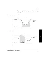
The Conductron heat-loss sensor uses Granville-Phillips’ Conductron
sensor proprietary geometry and control circuitry. The sensor is comprised
of two coplaner wire elements, a sensing wire, and a compensating wire
that corrects for ambient conditions. The resistance of the sensing wire
increases as its temperature increases. The controller continually adjusts a
heating current that flows through the sensing wire to keep the sensor at a
regulated temperature.
If pressure increases, the heat loss through gas conduction from the sensor
increases, and the sensor temperature decreases, causing the resistance of
the sensor to decrease. As this occurs, an error amplifier senses a change in
the resistance differential between the sensor element and the
compensation element, and generates an increase in the heating current
through the sensor. The increased current through the sensor increases its
temperature (and its resistance), and the resistance differential between the
two elements is reestablished at a higher sensor input voltage and current.
When calibrated, using a series of pressures and ambient temperatures, the
input voltage and current are measured as an indication of the system
pressure.
S
Ion current
Emission current
Pressure
×
----------------------------------------------------------------------
=
Summary of Contents for 356 Micro-Ion Plus Series
Page 2: ......
Page 24: ...24 Micro Ion Module Instruction Manual 356007 GP...
Page 58: ...Chapter 3 58 Micro Ion Module Instruction Manual 356007 GP...
Page 74: ...Index 74 Micro Ion Module Instruction Manual 356007 GP...
Page 75: ......

