background image

Instruction manual part number 356007-GP

Revision D - April 2018

Series 356

Instruction Manual

Series 356 Micro-Ion

®

 Plus

Vacuum Gauge Module

Customer Service / Technical Support:

MKS Pressure and Vacuum Measurement Solutions

MKS Instruments, Inc.
6450 Dry Creek Parkway
Longmont, Colorado 80503 USA
Tel: 303-652-4400
Fax: 303-652-2844
Email: mks@mksinst.com 

MKS Corporate Headquarters

MKS Instruments, Inc.
2 Tech Drive, Suite 201
Andover, MA 01810 USA
Tel: 978-645-5500
Fax: 978-557-5100
Email: mks@mksinst.com

Summary of Contents for 356 Micro-Ion Plus Series

Page 1: ...Series 356 Instruction Manual Series 356 Micro Ion Plus Vacuum Gauge Module Instruction manual part number 356007 GP Revision D April 2018...

Page 2: ......

Page 3: ...Ion are registered trademarks and mksinst TM is a trademark of MKS Instruments Inc All other trademarks and registered trademarks are the properties of their respective owners Customer Service Technic...

Page 4: ...g output no display 356001 Y Module with RS 485 interface analog output digital display 356002 Y Ion Gauge Filaments Yttria coated iridium Y Flange Fitting NW16KF D NW25KF E NW40KF K 1 33 inch NW16CF...

Page 5: ...ensor 23 2 3 Eliminating Radio Frequency Interference 23 Chapter 3 Operation 25 3 1 Preparing to Operate the Module 25 3 2 Theory of Operation 26 3 3 Set the Micro Ion Gauge Emission Current Threshold...

Page 6: ...356007 GP Chapter 4 Maintenance 59 4 1 Customer Service 59 4 2 Troubleshooting 60 4 3 Micro Ion Gauge Continuity Test 63 4 4 Replacing the Gauge Assembly 66 4 5 Returning a Micro Ion Module for Servic...

Page 7: ...terface Chapter 4 explains troubleshooting Micro Ion gauge testing removal and replacement and module return procedures Appendix A explains filament operation modes of the Micro Ion Gauge 1 2 Caution...

Page 8: ...tain a potential near that of the high voltage electrode during this coupling Potential fatal electrical shock could then occur because of the high voltage between these exposed conductors and ground...

Page 9: ...g the product Retain instructions Retain the instructions for future reference Follow instructions Follow all installation operating and maintenance instructions Heed warnings and cautions Adhere to a...

Page 10: ...Torr 2 66 x 10 2 mbar 2 66 pascal with decreasing pressure Micro Ion gauge auto off 3 x 10 2 Torr 3 99 x 1 2 mbar 3 99 pascal with increasing pressure Micro Ion gauge degas Electron bombardment 3 75 W...

Page 11: ...a 1 digit exponent and a sign for the exponent Trip point indicators optional LED indicator for relay 1 or relay 2 is solid green when corresponding relay is activated or blinks green when correspond...

Page 12: ...ust be certified to IEC standard with a safety extra low voltage classified output Operating environment 10 C to 40 C ambient non condensing indoor use only ordinary protection for moisture maximum al...

Page 13: ...acuum chamber 4 Assemble and connect the module wiring 5 Calibrate the Conductron sensor at atmosphere This chapter also explains what to do if radio frequency interference RFI from the module disrupt...

Page 14: ...and the guidelines below For proper operation of the module at atmosphere orient the module vertically see Figure 2 1 Although the Micro Ion gauge will read correctly below 100 Torr with the module m...

Page 15: ...module near a gas inlet or other source of contamination where inflow of gas or particulates causes atmospheric pressure to be higher than system atmosphere Do not locate the module where it will be e...

Page 16: ...cuum chamber can damage the module s internal connections Do not twist the module to tighten the fitting Use appropriate tools to tighten the fitting Table 2 1 Fittings for the Micro Ion Plus Module F...

Page 17: ...th stainless steel bolts and a new clean stainless steel with OFHC copper gasket Avoid scratching the seal surfaces a Finger tighten all bolts b Use a wrench to continue tightening 1 8 turn at a time...

Page 18: ...eed the 1 5 A peak Typical module operating power is 18 W for 4 mA emission when the Micro Ion gauge is ON Power inputs are reverse bias protected The Micro Ion gauge will not activate and an emission...

Page 19: ...to pin 12 Pin 3 Filament status Output LOW Indicates an inoperable filament b Pin 4 Gauge status Output LOW Indicates Micro Ion gauge is ON b Pin 5 Ground Input Power supply ground Pin 6 Degas status...

Page 20: ...Outputs The module provides an open collector output with no pull up as illustrated in Figure 2 5 Figure 2 5 Output Circuit Wiring User interface input pin pins 1 7 9 and 11 Internal to P input port...

Page 21: ...nnector Figure 2 6 Trip Point Relay 9 pin Connector Table 2 3 Trip Point Relay 9 pin Connector Pins Pin Function Input Output Voltage Level These voltage levels apply ONLY for resistive or non inducti...

Page 22: ...Micro Ion gauge ON and 250 Vdc during Micro Ion gauge degas Figure 2 7 Ground Connections WARNING Improper grounding could cause product failure or personal injury Follow ground network requirements f...

Page 23: ...ith U S Federal Communications Commission FCC limits for a Class A digital device pursuant to Part 15 of the FCC rules These limits provide reasonable protection against harmful interference when the...

Page 24: ...24 Micro Ion Module Instruction Manual 356007 GP...

Page 25: ...m detailing the Analog Output connections 5 Develop a diagram of the connections to the RS 485 I O status and control lines of the 15 pin User Interface connector 6 Develop a circuit schematic that sp...

Page 26: ...on Gauge Operation The functional parts of the Micro Ion gauge are the filaments cathodes grid anode and an ion collector as illustrated in Figure 3 1 These electrodes are maintained by the controller...

Page 27: ...ville Phillips Conductron sensor proprietary geometry and control circuitry The sensor is comprised of two coplaner wire elements a sensing wire and a compensating wire that corrects for ambient condi...

Page 28: ...trol electronics mixes the signals As the pressure is further reduced the Micro Ion gauge switches from low emission to high emission As pressure increases the opposite occurs at slightly higher press...

Page 29: ...ar 6 6 x 10 4 pascal then switches back to low emission at 1 x 10 5 Torr 1 3 x 10 5 mbar 1 3 x 10 3 pascal The emission switching pressures may need to be changed to adapt to the pressures of your pro...

Page 30: ...n gauge and exists for all ion gauges with tungsten filaments The catalog number on the Micro Ion Plus Module will indicate whether your module has yttria coated iridium filaments or tungsten filament...

Page 31: ...relay or switch can be used to perform this function To turn ON the Micro Ion gauge the process relay will close the switch To turn OFF the Micro Ion gauge the process relay will open the switch If t...

Page 32: ...onal Numeric Display Pressure values in the 10 10 range such as 6 x 10 10 will be displayed as 0 6 9 The resolution of the numeric display changes over the operating range of the module See Table 3 4...

Page 33: ...lculate output voltage from pressure To convert Torr to mbar multiply PTorr by 1 333 To convert Torr to pascal multiply PTorr by 133 3 Table 3 4 Display Resolution vs Conductron Sensor Pressure Measur...

Page 34: ...cate degas in progress Figure 3 7 illustrates the degas button and LED on the module control panel You can also install a switch between pins 6 and 7 on the 15 pin subminiature D connector to enable M...

Page 35: ...dic resets of the atmospheric pressure calibration point will improve the accuracy and repeatability of the Conductron sensor near atmospheric pressure Because performance varies depending on the proc...

Page 36: ...mbar 0 13 pascal 1 Turn ON the pump and allow the vacuum chamber to decrease to a pressure of 1 x 10 4 Torr 1 33 x 10 4 mbar 1 33 x 10 2 pascal or a lower pressure 2 Press the CAL button or toggle pin...

Page 37: ...at a lower pressure than the activation pressure as illustrated in Figure 3 10 Figure 3 9 Relay Behavior with Decreasing Pressure Figure 3 10 Relay Behavior with Increasing Pressure Deactivate Activa...

Page 38: ...s and LEDs The corresponding LED flashes to indicate the selected trip point Figure 3 11 Trip Point Buttons and LEDs Table 3 6 indicates the status of trip point indicators during operation and config...

Page 39: ...direction for each relay 6 If desired select the appropriate polarity for the trip point If you wish to change the trip point polarity press the up arrow or down arrow to scroll the display through t...

Page 40: ...on 3 17 RS 485 Commands Section 3 18 and Section 3 19 3 13 RS 485 Physical Layer Table 3 8 RS 485 Physical Layer Specifications Function Description Arrangement 2 wire half duplex Address range 0 to 6...

Page 41: ...et the address follow these steps 1 Send an SA set address offset command to the module The example SA command sets the address offset to 30hex 48 Example SA command from host 01SA30 Response from mod...

Page 42: ...st issues a command then waits for a response from the module Figure 3 13 illustrates the request and response data timing sequence including The request sent by the host response sent by the module M...

Page 43: ...to receive 1 2 msec minimum 12 0 msec maximum Time TR data processing and response time Time TP data processing time See Table 3 11 Time D time for module to switch from transmit to receive 200 sec m...

Page 44: ...y cause a garbled response from the module The symbol at the end of the command represents the carriage return CR which is entered as hex code 0D or if you re using a terminal by simultaneously pressi...

Page 45: ...on and have default values Table 3 13 RS 485 Command Set for Values not Affecting Module Operation Command Command Type Non volatile Change After Reset Data Returned Can be Locked See Page IGS Read No...

Page 46: ...Relay deactivates at 10 above activation pressure No Confirm or state No 53 PCP Read write Yes Relay activates with decreasing pressure No Confirm or state No 53 RST Write No None not applicable No No...

Page 47: ...odes IGS Read the Micro Ion Gauge ON OFF Status When you send the ion gauge status IGS command the module returns a character string that indicates the ON OFF status of the Micro Ion gauge IGS command...

Page 48: ...s Send the read status RS command to read RS 485 character strings that indicate the module operating status RS command from host 01RS Example response from module 01 00 ST OK The example response ind...

Page 49: ...Solution 00 ST OK Module is operating normally No solution necessary 01 CGBAD Conductron sensor is inoperable Cycle power to the module If necessary replace the gauge assembly see page 66 05 IG HV Mi...

Page 50: ...host 01DG0 Response from module 01 PROGM OK IG Ion Gauge Commands The RS 485 command includes the alpha characters I and G and the numeric value 0 OFF or 1 ON Send the ion gauge OFF IG0 command to tur...

Page 51: ...T command sets the additional delay time to 20 seconds Example IDT command from host 01IDT 20 Response from module 01 PROGM OK The command includes the alpha characters I D and T and the numeric value...

Page 52: ...R 1 00E 06 Response from module 01 PROGM OK The example SER command sets a value of 1 x 10 6 for the pressure at which the Micro Ion gauge switches from high to low emission current To read the emissi...

Page 53: ...gure 3 9 on page 37 The example process control polarity PCP command causes relay 1 to activate with increasing pressure Example PCP command from host 01PCP1 Response from module 01 PROGM OK The PCP1...

Page 54: ...e normal range for the offset of the Conductron sensor See page 57 to troubleshoot the problem The Micro Ion gauge will turn ON after the TZ command has been sent SU Set the Pressure Unit The example...

Page 55: ...ons are already unlocked the module returns a SYNTX ER response see page 57 You can unlock all locked functions by sending the TLU command If you attempt to reprogram a locked function without sending...

Page 56: ...485 version of the module After you ve reconfigured the module you must cycle power to the module before the new settings will take effect You may restore parameters listed in Table 3 19 to their defa...

Page 57: ...re the number of seconds in the IDT command is 0 to 600 then re send the IDT command see page 51 XX SYNTX ER Command was improperly entered Module does not recognize command syntax Re enter the comman...

Page 58: ...Chapter 3 58 Micro Ion Module Instruction Manual 356007 GP...

Page 59: ...responsibility For Customer Service Technical Support MKS Pressure and Vacuum Measurement Solutions MKS Instruments Inc 6450 Dry Creek Parkway Longmont Colorado 80503 USA Tel 303 652 4400 Fax 303 652...

Page 60: ...n Do not operate the module with static sensitive devices or other components removed from the product Do not handle static sensitive devices more than absolutely necessary and only when wearing a gro...

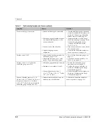
Page 61: ...inrush current see page 18 Replace or repair the power supply wiring see page 18 Reconnect the wiring to the power supply connector see page 18 Process control trip point does not function properly Tr...

Page 62: ...ds OFF Gauge button has been pressed the Micro Ion gauge is OFF Connection between pins 1 and 5 on the 15 pin connector is open Turn ON the Micro Ion gauge see page 31 Check the circuit and cables see...

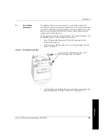
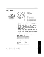
Page 63: ...um leaks or other materials contaminants within the gauge The gauge can be left on the system for the test The module electronics will be removed to gain access to the pins on the gauge 1 Turn OFF pow...

Page 64: ...64 Micro Ion Module Instruction Manual 356007 GP Figure 4 2 Removing the Gauge Step 3 Figure 4 3 Micro Ion Plus Replacement Gauge Carefully unplug the module electronics from the gauge Micro Ion Gauge...

Page 65: ...case The reading should be 100 M 6 Measure the resistance between pins 4 and 6 the grid pins The reading should be 2 7 Measure the resistance of pin 5 the collector pin to the gauge case The reading...

Page 66: ...n the vacuum system 8 Calibrate the Micro Ion Module at atmosphere see page 35 9 If Micro Ion gauge does not turn ON at 20 mTorr 2 66 x 10 2 mbar 2 66 pascal with decreasing pressure calibrate the Mic...

Page 67: ...urn filament 2 ON gauge LED will flash red After the gauge button has been pressed filament 2 turns ON Default mode for Micro Ion gauge with tungsten filaments Table A 2 Micro Ion Gauge Gauge LED and...

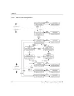
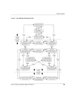
Page 68: ...Appendix A 68 Micro Ion Module Instruction Manual 356007 GP Figure A 1 Automatic Filament Switching Flow Chart...

Page 69: ...Filament Operation Micro Ion Module Instruction Manual 356007 GP 69 Figure A 2 Alternating Filament Switching Flow Chart...

Page 70: ...70 Micro Ion Module Instruction Manual 356007 GP Figure A 3 Manual Filament Switching Flow Chart...

Page 71: ...on 8 F Factory defaults 56 Firmware version 48 Fittings ConFlat flange 17 NW flange 17 VCR type 17 G Gauge assembly 66 Ground wiring 22 I Installation analog and RS 485 output wiring 18 attach module...

Page 72: ...keyboard unlock 56 keyboard unlock status 49 Micro Ion gauge ON OFF 31 preparing for 25 read firmware version 48 read module status RS 485 strings 48 read vacuum pressure 32 reset to power up state 54...

Page 73: ...ent range 10 RS 485 output 11 trip point indicators 11 trip point relays 11 System Grounding 8 T Temperature 12 Theory of operation Conductron sensor 27 Micro Ion gauge 26 Trip point relays 36 contact...

Page 74: ...Index 74 Micro Ion Module Instruction Manual 356007 GP...

Page 75: ......

Page 76: ...Service Technical Support MKS Pressure and Vacuum Measurement Solutions MKS Instruments Inc 6450 Dry Creek Parkway Longmont Colorado 80503 USA Tel 303 652 4400 Fax 303 652 2844 Email mks mksinst com...

Reviews: