46
937A Multi-Sensor System
Relay Set Points Mode
The
Relay Set Points mode is used to review and set the pressure at which
the set point relays switch.
Five setpoint relays are available; one for Slot
CC and two each for Slots A
and
B. If a single channel module is used in Slots A or B, both relays are
controlled by the first channel of the module. Each setpoint for the slot
may be adjusted independently.
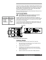
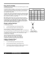
The SPDT relay contacts are accessible through the rear panel
Accessory
connector on the power supply module. A mating connector kit is provided
with the Series 937A System. The relays are rated for use at 2 A at 30 V.
See the table to the left for pin assignments.
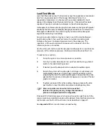
SP1 to SP5 indicators appear when the set point relays are energized.
When an indicator is on, the measured pressure on that channel is below
the set point value, the normally open relay contact is closed, and the
normally closed contact is open. When an indicator is off, the measured
pressure is above the set point value, the normally open relay contact is
open, and the normally closed contact is closed.
Reading a Relay Set Point
To read the set point value,
1
Turn the
Function Select switch to Relay Set Points.
2
Set the
Gauge Select switch to the desired set point.
Set point relays are not disabled while in
Relay Set Points
mode. Set point values can be reviewed without process control interference.
If the
Gauge Select switch is set to a slot with no module, N O will appear on
the display line of the selected channel. The channels which do have
modules will also be displayed.
The actual relay trip point and the set point displayed may
differ due to hysteresis. The hysteresis is most noticeable
where the sensor's pressure-vs-voltage curve is relatively flat
(near the top or bottom of a pressure range for most sensors).
Setting a Relay Set Point
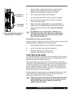
To change the set point pressures,
1
Turn the
Function Select switch to Relay Set Points.
2
Set the
Gauge Select switch to the desired set point.
3
Press the
Up or Down push-button to increase or decrease the set
point. Holding the button changes the set point faster.
Male, 15-pin "D"
Accessory
connector
15 Pin Accessory Connector
Set
Point
Channel
Normally
Open
Normally
Closed
Common
1
CC
2
1
9
2
A1
10
3
11
3
A2
12
4
5
4
B1
13
6
14
5
B2
7
8
15


