background image

INSTALLATION & MAINTENANCE MANUAL 


These instructions should be read carefully and retained after installation by the end user for future reference 

and maintenance. 

These instructions should be used to aid installation of the following product: 

EMPOWER3 
SAFETY 


This product must be installed in accordance with the latest edition of the IEE Wiring Regulations 

(BS7671) and current Building Regulations. If in any doubt, consult a qualified electrician 


Please isolate mains prior to installation or maintenance 


Check the total load on the circuit (including when this luminaire is fitted) does not exceed the rating of 

the circuit cable, fuse or circuit breaker 


Please note the IP (Ingress Protection) rating of this luminaire when deciding the location for 

installation 


Allow 50mm above and around the fitting for air dissipation (do not cover the fitting with insulation) 


This product is Class II double insulated  


This product is IP20 rated 

INSTALLATION 


Provide power to the required point of installation  


Cut a suitable hole in the mounting surface as per the cut-out details (see Fig. 1) ensuring not to 

infringe with any joists, gas/water pipes or electrical cables  


Fig. 1 


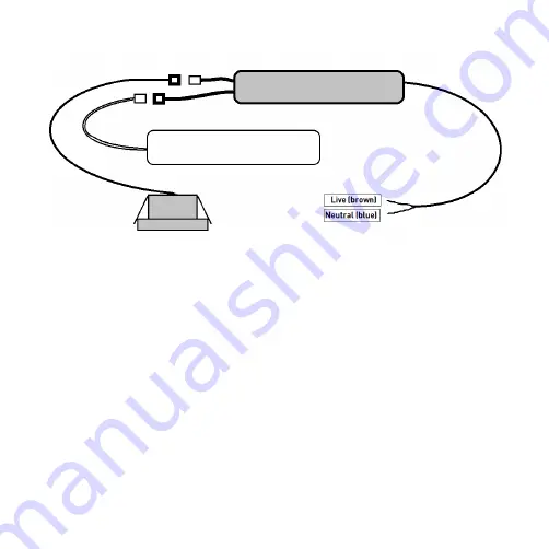
Connect the luminaire to the mains supply via a suitable junction box ensuring that correct polarity is 

observed: Live (brown) and Neutral (blue) (see Fig. 2) 


Fig. 2 


Connect the battery to the inverter via the plug and socket provided, ensuring that correct polarity is 

observed 

• Connect the battery to the inverter via the plug and socket provided, ensuring correct 
   polarity is observed
• Connect the downlight to the inverter via the plug and socket provided
• Change the bezel, if required, by unscrewing from the downlight and replacing with the 
   required bezel
• Place the inverter and battery into the ceiling via the cut-out
• Lift both spring clips on the sides of the fitting and push into the ceiling
• Switch on and check for correct operation, ensuring the green indicator LED is illuminated
• We recommend, on commissioning the installation, a minimum charge period of 24 hours 
   before carrying out an emergency duration test

Fig. 2

Summary of Contents for EMPOWER3

Page 1: ...INSTALLATION MAINTENANCE MANUAL EMPOWER3 ...

Page 2: ...gulations If in any doubt consult a qualified electrician Please isolate mains prior to installation or maintenance Check the total load on the circuit including when this luminaire is fitted does not exceed the rating of the circuit cable fuse or circuit breaker Please note the IP Ingress Protection rating of this luminaire when deciding the location for installation Allow 50mm above and around t...

Page 3: ... Ingress Protection rating of this luminaire when deciding the locatio installation Allow 50mm above and around the fitting for air dissipation do not cover the fitting with i This product is Class II double insulated This product is IP20 rated TALLATION Provide power to the required point of installation Cut a suitable hole in the mounting surface as per the cut out details see Fig 1 ensurin infr...

Page 4: ...ity is observed Connect the downlight to the inverter via the plug and socket provided Change the bezel if required by unscrewing from the downlight and replacing with the required bezel Place the inverter and battery into the ceiling via the cut out Lift both spring clips on the sides of the fitting and push into the ceiling Switch on and check for correct operation ensuring the green indicator L...

Page 5: ...cessories reserve the right to alter product specification without prior notice The LED lamps fitted in this product are non replaceable The product should be recycled in the correct manner when it reaches the end of its life Check local authorities for where facilities exist The batteries in this luminaire are Lithium Ion and must be disposed of correctly Please contact the local authorities for ...

Page 6: ... off circuit breaker Ensure normal supply is restored after test and ensure charge indicator is illuminated Annual 3 hour duration test simulate a mains supply failure for 3 hour continuous test by operation of key switch or switching off circuit breaker Ensure normal supply is restored after test and ensure charge indicator is illuminated If the luminaire fails any of the above tests please conta...

Page 7: ...AR THIRD YEAR FOURTH YEAR FIFTH YEAR SIGNED DATE SIGNED DATE SIGNED DATE SIGNED DATE SIGNED DATE 1 FUNCTIONAL 2 FUNCTIONAL 3 FUNCTIONAL 4 FUNCTIONAL 5 FUNCTIONAL 6 FUNCTIONAL 7 FUNCTIONAL 8 FUNCTIONAL 9 FUNCTIONAL 10 FUNCTIONAL 11 FUNCTIONAL 12 3 HOUR Installed by Installation date Contact number ...

Page 8: ...AVSEP21_V2 ML Accessories Limited LU5 4LT www mlaccessories co uk 54 INTERNATIONAL CONTACT DETAILS INTERNAT CONTACT D 5 60 C TA ...

Reviews: