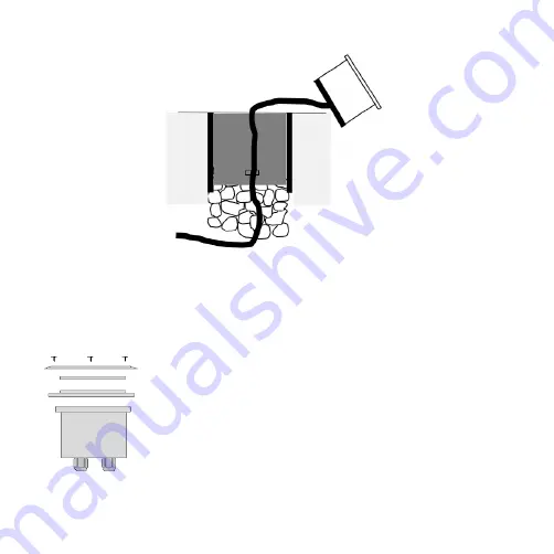
• There must be enough cable below the luminaire to carry out maintenance work (see Fig. 3)
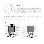
Fig. 2
•
There must be enough cable below the luminaire to carry out maintenance work (see Fig. 3)
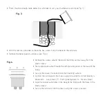
Fig. 3
•
With the Allen key provided, remove the hex screws fixing the bezel to the luminaire
•
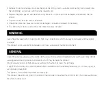
Remove the bezel, gasket and glass (see Fig. 4)
Fig. 4
•
Remove the screws around the top of the fitting and pull away from the plastic sleeve
•
Feed appropriate cable through the compression glands at the base of the fitting
•
Secure the sleeve (if required) into the mounting surface
•
Connect the luminaire to the mains supply ensuring the correct polarity is observed L - Live (brown), E
- Earth (green/yellow), N - Neutral (blue)
Fig. 3
• With the Allen key provided, remove the hex screws fixing the bezel to the luminaire
• Remove the bezel, gasket, and glass (see Fig. 4)
Fig. 2
•
There must be enough cable below the luminaire to carry out maintenance work (see Fig. 3)
Fig. 3
•
With the Allen key provided, remove the hex screws fixing the bezel to the luminaire
•
Remove the bezel, gasket and glass (see Fig. 4)
Fig. 4
•
Remove the screws around the top of the fitting and pull away from the plastic sleeve
•
Feed appropriate cable through the compression glands at the base of the fitting
•
Secure the sleeve (if required) into the mounting surface
•
Connect the luminaire to the mains supply ensuring the correct polarity is observed L - Live (brown), E
- Earth (green/yellow), N - Neutral (blue)
• Remove the screws around the top of the fitting and pull away from the
plastic sleeve
• Feed appropriate cable through the compression glands at the base of the
fitting
• Secure the sleeve (if required) into the mounting surface
• Connect the luminaire to the mains supply ensuring the correct polarity is
observed L - Live (brown), E - Earth (green/yellow), N - Neutral (blue)
• Align the countersunk holes in the body of the fitting with the holes in the
plastic sleeve
• Secure the luminaire into the sleeve using the screws provided
Fig. 4


