background image

Skylle 1550 User Manual 20181107V2 

|30


8

 / 

31


LANDING GEAR ASSEMBLY


Step 1:


Step 2:


Step 3:


Take the landing leg and connect the 
carbon rod through the holes in the 
landing leg on both sides.


Tighten the screws in the landing leg.


Connect the landing gear with the body and 
tight it with the given plastic nut.


BATTERY STRAPPING


Step 1:


Step 2:


Place the battery and strap the battery with 

Velcro s

traps.


Connect the battery connector to the drone and 
close the cap.


Summary of Contents for Skylle 1550

Page 1: ...Yihe Road MMC Tech Park Shiyan Street Bao an District Shenzhen City Guangdong Province PR China Monday Friday 9am 6pm SMC6 1550 This model is available in black and white All circuits and RF modules...

Page 2: ...y Landing Gear Battery Strapping 4 AIRCRAFT UAS PROFILE 9 Flight Controller Flight Modes Indicator Signals 5 REMOTE CONTROLLER 11 Key Features Contents and Technical Specifications Stick Adjustment Co...

Page 3: ...issafe tooperate CAUTION Always remove propellers blades when assembling setting up parameters repairing and performing maintenance This will avoid any negligence methods When it is turned on make sur...

Page 4: ...tured with GPS hover system constant speed cruise control pointing flight and automatic route flight functions FEATURES AND HIGHLIGHTS Flight Battery A Couple of 22000mAh lithium polymer ion flight ba...

Page 5: ...per easy to plug into the drone no tool needed 4 Supported maximum 13 channels 5 Eachchannelcanbecustomizedtomeettherapidreplacementoftheusageofmultiplepayloads channels include 3 power channel 1 BAT...

Page 6: ...rBattery Charger GroundStation Battery Charger Payloads Landing Gear Transmission Antenna Battery Checker 3 ASSEMBLY BODY ARM ASSEMBLY Step 1 Step 2 Takethe arm and insert to the body according to the...

Page 7: ...he carbonrodthroughtheholesinthe landing leg on both sides Tightenthescrewsinthelandingleg Connectthelandinggearwiththebodyand tight it with the given plastic nut BATTERY STRAPPING Step 1 Step 2 Place...

Page 8: ...can achievethe height lock and position lock functions byusing theIMU and the GPS to control the aircraft Please carry out the following procedures to finish assembly configuration and flight testing...

Page 9: ...o maintain copter stability with altitude GPS Mode GPS mode uses on board GPS for stable flying reliable only on GPS LED INDICATOR SIGNALS Control Mode GPS signal Manual Mode No indicator Best 6 No in...

Page 10: ...commended to fly WhentheLEDblinks 4 please contact your dealer 5 REMOTE CONTROLLER INTRODUCTION MMC uses Futaba T14 channels remote controller model 1 right hand throttle as a standard one Specific fu...

Page 11: ...ion Selectsafunctionthatalertstheoperatortovariousalarmsandtimersbyvibratingthetransmitterinadditiontosoundingabuzzer CONTENTS AND TECHNICAL SPECIFICATIONS 14SG includes the following components Trans...

Page 12: ...an choose switch and set the ON OFF direction in the setting screen of the mixing functions Digital Trim Digital Trim T1 T2 T3 and T4 This transmitter is equipped with four 4 digital trims Each timeyo...

Page 13: ...e screen title item and touch the RTN button to return to the home screen from a menu screen Note Scroll operation circleyour fingerontheouter edgeofthe RTNbutton Thesensorsmaymis read your touch as a...

Page 14: ...urn type stick lever can be adjusted 1 First removethebatterycoveronthebottomofthetransmitter Next unplugthebatterywireandremovethebatteryfromthetransmitter 2 Next usinga hand removethetransmitter ssi...

Page 15: ...all each setting screen and touch the RTN button The setting screen appears User Menu A user menu which allows the user to customize and display frequently used functions has been added a When the U M...

Page 16: ...dio waves The left and right LED monitors will change to solid red How to stop the transmitter Turn off the power switch of the transmitter The transmitter shuts down at once Low battery alarm and aut...

Page 17: ...ach 5KM It comes with a USB3 0 HD video storage card for faster and more stable data transmission It can display both Video and flight data and it s easy to switch between these twodisplays mode Finge...

Page 18: ...e the user can control the UAS and the mounting equipment simultaneously displaying the images transmitted by the drone in real time INSTALLATION Operating system requirements Windows 7 Windows 8 Wind...

Page 19: ...id map Data Save Select whether to save flight data after each flight AutomaticConnection Selecttoautomaticallyconnecttothedronewhenthereisa drone connection unselecttousethemanualconnectiondrone ifit...

Page 20: ...arning It is not recommended for inexperienced non professionals to calibrate this function If the sensor malfunctions please contact us for customer service 5 PROPELLERS AND WINGS TEST Followthepromp...

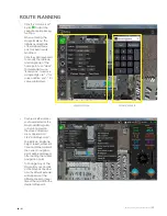
Page 21: ...ve a single digit use for value addition use for value subtracted Waypoint Menu Virtual Keyboard 2 Double clickthelocation youhaveselectedonthe maptoaddWaypoints or byalongpresson the screen dropdown...

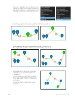
Page 22: ...drag it to modify the position of the waypoint 5 Select thesecond waypoint Long press the screen click the insert the waypoint Ifclicking add land point andaddonelandpointnexttothewaypointof4 6 Ifyou...

Page 23: ...accordingly Sync Accessibility 2 Themissioncan be downloadedfrom thedrone After long pressing the screen click Mission Check and download from the drone Or go into Sync click Load From Vehicle to rece...

Page 24: ...ble of inputting parameters every time 2 Image coverage is changeable at front and side coverage 3 Change the angle of the waypoint in the drawing area by changing the grid angle 0 degrees in the nort...

Page 25: ...to the position you want to modify 3 Completetheadjustmentbyclickingthe FinishAdjustment orbyright clickingonthe map area 4 PATH ADJUSTMENT selective use as needed Click the Transpose button to contr...

Page 26: ...rrent positionandadjustthedirectionofthenosewhilethe aircraftisflyingintheair Thisfunctionalsocanbe used to move the aircraft forward and backward in the direction of themap Clicktheupperrightofthegro...

Page 27: ...harger listenfor beeping alerts Battery Life Thebatterylifemetercanbecheckedusingeitherthebatterycharger priortoflight aportableLiPoVoltageCheckerand Balancer not included or byviewingtheOSDontheFPVsc...

Page 28: ...BATTERIES CHARGED UASFlightBatteries Radio controller Telemetry Ground Station s Sensor s Comms radios GROUND STATION Laptop charged and updated Tablet charged and updated LCD Screen tested and workin...

Page 29: ...ies mountedcorrectly Antennasonandfoldedout SDCardinUAS Payload CG checked Flightareaclear Takeoffandlandingareasafe Checkwindconditions Controller on and transmitting GroundStation onandconnects UAS...

Page 30: ...PS FedEx etc Each productis carefully packaged toprevent shippingdamage MMChasnocontrol overtheinternal processes delaysofMail Carriers nor will be held liable for any damages mistakes custom holds lo...

Page 31: ...ates uses and can radiate radio frequency energy and if not installed and used in accordance with the instructions may cause harmful interference to radio communications However there is no guarantee...

Reviews: