background image

30 

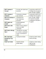
MSP Command 
Corrupt 

Corrupt command was 
received.   

Connection with the PC 
(Configurator program) 
went wrong, try again. 

MSP Command 
Unknown 

Unknown command 
was received. 

Connection with the PC 
(Configurator program) 
went wrong. Update 
Firmware or update 
Configurator Software. 
Try again. 

MSP Sub Command 
Unknown 

Unknown Sub 
Command was 
received. 

MSP Argument 
Invalid 

Invalid argument 
received. 

MSP Device Not 
Ready 

Device as not ready to 
receive an MSP 
command. 

MSP Device Wrong 
State 

The device is not able 
to receive a command 
in the current device 
state. 

PCB Test Failed 

Factory test failed. 

A fault occurred during 
factory testing. 

Application Test 
Failed 

Field Test Failed 

Field test failed 
(Calibration). 

A fault occurred during 
field testing 
(Calibration). 

Summary of Contents for P012-62

Page 1: ...User Installation Manual EN Hand Warmer Adjustable heating device Hand Warmer P012 62 ...

Page 2: ...kstraat 15 D 9850 Nevele Belgium Website www mo vis com E mail contact mo vis com Telephone 32 9 335 28 60 Hand Warmer User Installation manual Produced and published by mo Vis bvba Belgium Edition October 2016 Manual item D P012 62 70 00 ...

Page 3: ...ts 6 Warranty 7 Safety precautions 9 Design and function of the Hand Warmer 13 Parts and accessories 13 mo Vis Configurator software 17 Installation instructions 18 Preparations 18 Installation of the Hand Warmer 20 Operation of the Hand Warmer 22 First time use 24 Using the Hand Warmer 26 Conditions of use 26 User adjustments 27 Troubleshooting 28 Error codes 29 Maintenance 32 ...

Page 4: ...4 Parameter settings 33 Technical data 35 ...

Page 5: ...tor software The operating instructions are primarily intended to acquaint you with the functions and characteristics of the mo Vis product and how you can use it in the best manner possible They also contain important safety and maintenance information as well as describe possible problems that can arise during use Always keep the operating instructions handy in connection with your wheelchair si...

Page 6: ...hnical problems we advise you to contact your dealer If the dealer is not available or unknown please contact mo Vis bvba by email support mo vis com or by phone 32 9 335 28 60 Always state the device serial number when contacting mo Vis This ensures you are provided with the correct information Spare parts and accessories Spare parts and accessories must be ordered by the dealer at mo Vis bvba Sc...

Page 7: ...ser from an authorised mo Vis dealer Start of the warranty period Each warranty shall begin on the date the product is first delivered to the customer Repair and replacement For warranty service we advise you to contact the dealer from whom the product was purchased In the event of a defect in material or workmanship the dealer must obtain a return authorisation RA number from mo Vis and the produ...

Page 8: ...material or construction Amendments No person is authorised to alter extend or waive the warranties of mo Vis Voiding of warranties The foregoing warranties are contingent upon the proper installation use maintenance and care of the product The warranty will be void if the product has been installed or used improperly or if it has been repaired or any part replaced by persons other than mo Vis or ...

Page 9: ...precautions General The Hand Warmer is intended to be fitted on any power wheelchair with 24 V connection Incorrect use or installation may lead to risk of injury to the user and damage to the wheelchair or other property In order to reduce these risks you should carefully read this instruction manual paying particular attention to the safety instructions and warning texts Any unauthorised use of ...

Page 10: ...rsonal injury or damage to the wheelchair CAUTION Please use caution where the symbol appears WARNING Please use extreme caution where the symbol appears Failure to observe warnings can lead to personal injury or property damage CAUTION Limited liability mo Vis accepts no liability for personal injury or damage to property that may arise from the failure of the user or other persons to follow the ...

Page 11: ...Medical Devices Directive No 93 42 EEC Hand Warmer complies with these limit values WARNING Assembly The Hand Warmer should only be installed or adjusted by a qualified service engineer or someone with adequate knowledge to perform the adjustment in an expert manner Maintenance and service Carry out only the service and maintenance activities specified in this manual as long as you comply with the...

Page 12: ...o changes which might impair the function and safety of the product It could also lead to the warranty becoming void CAUTION Testing The Hand Warmer should always be tested without any person sitting in the wheelchair after the physical installation of the Hand Warmer or adjustment of the parameters ...

Page 13: ...hich is powered by the wheelchair battery power 24V and contains its own control electronics Air is drawn at the front heated and forced out again at the front using an internal fan As the air inlet and outlet are at the same side warm air is recycled instead of using air from the cold environment This results in a huge advantage with regards to power consumption and efficiency Parts and accessori...

Page 14: ...ion Lead 180mm P012 40 Hand Warmer Mounting Set M012 45 Hand Warmer manual with Serial number sticker D P012 62 70 Hand Warmer Mounting Set The Hand Warmer Mounting Set M012 45 is included in the Hand Warmer Set P012 62 The Hand Warmer Mounting Set consists of the following parts ...

Page 15: ...Hand Warmer 15 Product description Product code Q2M half Clamp D6 bolt 14mm M004 04 Q2M Rod D6 50mm 1 piece M004 74 Hand Warmer Dual lock 22 9 3 5mm 2 pieces M012 40 ...

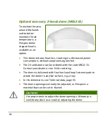
Page 16: ...comfort The 2 hands dome can be ordered with the code M012 31 Contact your dealer or mo Vis for ordering The dome is delivered with four hook and loop fastener pads to attach the dome to any flat surface e g a tray for its dimensions see Technical data page 35 The dome openings can easily be adjusted as Perspex is a material that can be cut or shaved CAUTION Use proper tools to adjust the dome ope...

Page 17: ...fully adjustable Software download You can download the software on the mo Vis website www mo vis com For all details on how to install and use the software we advise you to consult the manual of the mo Vis Configurator software included in the software download User profiles Depending on your profile user attendant dealer OEM you will be able to configure a number of parameters for the Hand Warme...

Page 18: ...the maximum heater temperature using the configurator to 70 C 158 F air will then be 60 C 140 F or less CAUTION The devices air inlet and outlet are both at the front Leave at least a distance of minimal 5 cm 2 in between the front of the device and any object WARNING The device has an open structure at the front Mount the device in such a way that no water rain can enter the device Some drops of ...

Page 19: ...temperature and supply voltage Whenever a fault is detected the device will switch itself of In case there would be an undetected fault the device contains an additional internal fast blow fuse of 4 A and a PTC fuse of 3 A Preparations Qualified service engineer Only a qualified service engineer may install the Hand Warmer Tools Use an Allen wrench to install the Hand Warmer Mounting Set and Hand ...

Page 20: ...ir and the user this plan should specify Where which part of the Hand Warmer should be placed How the Hand Warmer will be operated The Hand Warmer parameter settings Serial number sticker The additional serial number sticker included in the package has to be adhered to the back of this manual Installation of the Hand Warmer Mounting options The Hand Warmer can be mounted on any location on the whe...

Page 21: ...s are provided for placing these hook and loop fasteners Mounting using Q2M To install the Hand Warmer unit proceed as follows according to your installation plan 1 Define the place and position of the Hand Warmer on the wheelchair The Hand Warmer can be mounted on any location on the wheelchair 2 Secure the Q2M half clamp and bolt on the bottom of Hand Warmer housing 2 positions in 90 steps are p...

Page 22: ...nd connect the Hand Warmer Extension Lead included with the Hand Warmer connector and lead the XLR power cable to the wheelchair joystick or battery Secure the power cable to the wheelchair with straps or fasteners WARNING Make sure that cabling is mounted in such a way that excessive wear and tear is avoided WARNING The XLR power cable connector contains a fuse Use an adapter to connect to non XL...

Page 23: ...he device You can adjust the number of levels using the mo Vis Configurator software to alter the parameters The green LED at the front indicates the status of the device see table Mode LED indicator Sleep mode Off Stand by Short on very long off Active Level 1 Short on long off Active Level 2 Short on medium off Active Level 3 Short on short off Fault Number of flashes long off Parameter configur...

Page 24: ... why the device stopped First time use Dealer assistance During first time use by the user it is advised that the dealer or service engineer assists and explains the different possibilities to the customer the user and or his attendant If needed the dealer can make final adjustments User testing It is important that the customer is fully aware of the installation how to use it and what can be adju...

Page 25: ...rdance with client s needs Can the user safely operate the Hand Heater with the least effort Is the heating of the Hand Warmer in all available levels optimal for the user 3 If needed adjust the Hand Warmer and retest till optimal position and functioning 4 Explain to the customer possible problems and how to address them see Troubleshooting ...

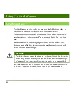
Page 26: ...st time use If the conditions of use change significantly please contact your dealer or a qualified service engineer to avoid excessive wear and tear or unintended damage WARNING The device has an open structure at the front Mount the device in such a way that no water rain can enter the device Some drops of water will not cause problems excess water must be avoided It is advised to use the 2 hand...

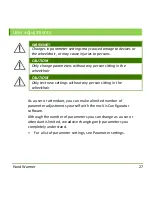
Page 27: ...e wheelchair CAUTION Only test new settings without any person sitting in the wheelchair As a user or attendant you can make a limited number of parameter adjustments yourself with the mo Vis Configurator software Although the number of parameters you can change as a user or attendant is limited we advise changing only parameters you completely understand For a list of parameter settings see Param...

Page 28: ...the table below Flash Count Reason Required action 1 2 3 Power Supply Under Over voltage Check power connections and power cable 4 Temp Sensor Replace PCB 5 Power Switch Replace PCB 6 ADC Internal Analog to Digital Converter Replace PCB 7 Test Flag failed or diagnostic failed Redo tests Replace PCB 8 CPU fault Replace PCB 9 Scheduler fault Update Software Replace PCB 10 Coding Error Update Softwar...

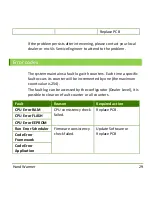
Page 29: ...ccurs its counter will be incremented by one the maximum count value is 254 The fault log can be accessed by the configurator Dealer Level it is possible to clear one fault counter or all counters Fault Reason Required action CPU Error RAM CPU consistency check failed Replace PCB CPU Error FLASH CPU Error EEPROM Run Error Scheduler Firmware consistency check failed Update Software or Replace PCB C...

Page 30: ...ry again MSP Sub Command Unknown Unknown Sub Command was received MSP Argument Invalid Invalid argument received MSP Device Not Ready Device as not ready to receive an MSP command MSP Device Wrong State The device is not able to receive a command in the current device state PCB Test Failed Factory test failed A fault occurred during factory testing Application Test Failed Field Test Failed Field t...

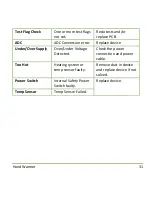
Page 31: ...ion error Replace device Under Over Supply Over Under Voltage Detected Check the power connection and power cable Too Hot Heating system or temp sensor faulty Remove dust in device and replace device if not solved Power Switch Internal Safety Power Switch faulty Replace device Temp Sensor Temp Sensor Failed ...

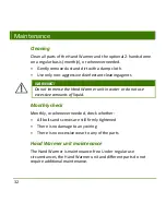
Page 32: ...o not immerse the Hand Warmer unit in water or do not use excessive amounts of liquid Monthly check Monthly or whenever needed check whether All bolts and screws are still firmly tightened There is no damage to any wiring There is no excessive wear to any of the parts Hand Warmer unit maintenance The Hand Warmer is maintenance free Under regular use circumstances the Hand Warmer unit and different...

Page 33: ... change a number of parameters Parameter Min Max Default Description Auto Off 0 600 240 The device will automatically switch off after a set time in minutes Changing the level using the button will reset the timer a value of 0 means the device will never switch off Levels 1 3 3 The number of available power levels Minimum Temp 40 80 50 The temperature in C of the heater at the lowest power level ...

Page 34: ...75 The temperature in C of the heater at the highest power level Minimum Fan Speed 10 100 20 The fan speed airflow in at the lowest power level Maximum Fan Speed 10 100 85 The fan speed airflow in at the highest power level ...

Page 35: ...ion code Hand Warmer Set P012 62 Hand Warmer Unit P012 61 Hand Warmer Dome Set M012 31 Hand Warmer Mounting Set M012 45 Hand Warmer Power Cable 180 mm P012 40 Dimensions Hand Warmer unit 50 mm x 29 mm x 29 mm HxWxD 1 97 in x 1 41 in x 1 41 in HxWxD ...

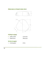
Page 36: ...36 Dimensions 2 hands dome cm Voltage supply Safety Limits 12 to 35V Normal Use 18 to 26V Current supply At full power 2 0 A ...

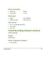
Page 37: ...eep mode 1 7 mA Cable length Pigtail 15 cm 0 49 ft Extension Lead 180 cm 5 9 ft XLR connector Pin 1 V internally fused 5 A Pin 2 GND Pin 3 NC Tested According relevant sections ISO7176 EN12184 Weight 125 g 4 4 oz Heater Temperature Shutdown 100 C 212 F ...

Page 38: ...38 Installation date Dealer Dealer stamp Serial number sticker ...

Reviews: