background image

4.1   MANUALLY MOVING THE BLADE

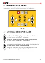
From the panel the left side up key can be used to manually activate

the valves to move the left side of the blade up.

Similarly the left side down key can be used to manually activate

the valves to move the left side of the blade down. 

From the panel the right side up key can be used to manually activate

the valves to move the right side of the blade up. 

Similarly the right side down key can be used to manually activate

the valves to move the right side of the blade down.


DOWN

UP


DOWN

UP

4.   WORKING WITH PANEL

Please refer to section 2.2 for Key Functions

.

 and Key Designators

ZERO

UP

DOWN

DOWN

UP

MAST

AUX 2

AUX 1

A

M

A

M

REF

+

-

figure 23

Summary of Contents for MCE Lasers DUO 2 v2

Page 1: ...OPERATOR S MANUAL DUAL MACHINE CONTROL PANEL WITH AUXILIARY OUTPUT HYDRAULIC AUX JOYSTICK S SENSOR S ZERO UP DOWN DOWN UP DUO v2 MAST AUX 2 AUX 1 12 24 V DC A M A M REF ver 5 16 DUO2 v2...

Page 2: ...________________________ Telephone ______________________________________ Facsimile _______________________________________ Email __________________________________________ P ublished By P MOBA Mobile...

Page 3: ...d f service in the field is necessary to repair I machine mounted equipment under warranty may authorize on MOBA Australia site repairs at no charge for parts and labour ravel time accommodation and T...

Page 4: ...9 3 7 Setting p ydraulics T H 20 3 7 1 Selecting ype of ydraulics S H Response 21 3 7 2 Adjusting ettings for ydraulic 1 General Settings for VO Hydraulics 22 3 7 2 2 General Settings for IO Hydraulic...

Page 5: ...36 Sensor 37 5 1 General Settings Adjustment 37 5 1 1 Response Adjustments 38 5 1 2 Dead Band A 39 5 1 3 Proportional Range djustment 39 5 1 4 Control Range Adjustment 40 5 1 5 Measurement Mode 40 5...

Page 6: ...sting Mast Position 47 3 5 5 4 Relative Offset 48 5 5 4 1 Using the Panel Keys 48 5 5 4 2 Using Optional Joystick 49 6 GNSS 51 Sensor 6 NSS Working Screen 51 1 G 6 2 GNSS Function Keys 51 6 3 GNSS Job...

Page 7: ...on menu enables the operator to set all necessary settings from accuracy selection for control to the selection of different valve types to be used In addition a three colour 5 channel LED clusters on...

Page 8: ...nfiguration menu A M Key changes the hydraulics valve control between two operating modes or manual mode automatic mode Aux Hyd Up and Down Keys to scroll through menu options t or o increase or decre...

Page 9: ...s section for graphical key equivalent of each key designator POWER key CONTROL PANEL MINI JOYSTICK MENU key ENTER key ZERO key MAST key REF key AUX1 key UP DOWN key A M key L R button RIGHT A M butto...

Page 10: ...ket blade by very little Green bar blinking no deviation centre or ON TARGET Inner orange arrow and green bar blinking very small downward deviation Need to raise the bucket blade by very little Inner...

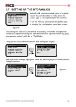
Page 11: ...guration main menu screen As discussed before the left side and right side submenu give access to settings related to hydraulics and sensor Using key scroll down to select the side and then press the...

Page 12: ...M A M REF ver 5 11 OPTIONAL Joystick A RS 052 or Joystick A RS 082 A RS 001 NC A RS 080 Optional Sensors 2 x Laser Receivers 1 x Laser Receiver 1 x Sonic Tracer 1 x Laser Receiver 1 x Slope Sensor 1 x...

Page 13: ...properly 2 Mount the IB DUO or IB DUO CAN Junction Box and connect it to the 2 2 connector labelled SENSOR S on the DUO using appropriate cable listed in 2 the table above 3 Mount both sensors on pos...

Page 14: ...foss ON OFF with PVEO actuator 2 Eaton Vickers KDG4V series 3 Rexroth 4WRAB6 This output is a low current voltage signal not intended to drive a solenoid directly Mainly used with Danfoss Proportional...

Page 15: ...icular hydraulic output type requirement for that valve Below are examples of how to connect the bare wires for each of the four hydraulic output types using as examples some common valve brands and a...

Page 16: ...ge DOWN1 PIN 2 Yellow SIG1 UP1 PIN 3 Not Connected GND Pink GND PIN 1 Pink GND PIN 2 Yellow SIG1 UP1 GND Pink GND Optional PIN 1 Pink GND PIN 2 Orange DOWN1 GND Not Connected Danfoss PVG series with P...

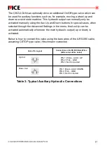
Page 17: ...dvanced Settings in the menu the Aux Up can be activated automatically whenever the main hydraulic output up or down is activated Below is how to connect this valve using the bare wires of the A RS 08...

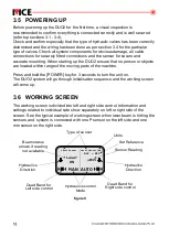
Page 18: ...the machine Press the key to turn the unit on and hold POWER for 3 seconds The DUO system will go through initialisation sequence and the working screen 2 will come up Laser Sensor 015 MAN AUTO Laser...

Page 19: ...ight side side Individually adjust the settings for left side control and right side control by going into submenu option Left Side or Right Side figure 10 Using key select the side and then press AUX...

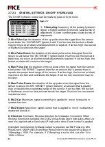
Page 20: ...lic Left Type VO General Settings Calibration Advance Settings Copy to Right Exit Hydraulic Left Proportional VO Proportional IO On Off Low Side On Off High Side MOBA Gateway Exit figure 12 When finis...

Page 21: ...s to optimise the hydraulic response To adjust these settings 1 key Use to select a setting and then press the key AUX2 ENTER 2 The setting will start to blink indicating editing mode Use that the uni...

Page 22: ...l is applied when the signal from the connected sensor is below the ON TARGET green band by an amount that is greater than or equal to the proportional range of the sensor If set to high the bucket o...

Page 23: ...an amount that is greater than or equal to the proportional range of the sensor If set to high the bucket or blade may o move too fast and overshoots the target If set too low movement may be too slo...

Page 24: ...is below the ON TARGET green band by an amount that is greater than or equal to the proportional range of the sensor If set to high the bucket or blade o may move too fast and overshoots the target If...

Page 25: ...cs menu using key select Calibration then press calibration AUX2 ENTER The following sections re a description of the calibration procedure for the left side A similar procedure should followed for th...

Page 26: ...inimum AUX2 M to for down 100 100 UP Down MIN Pulse Test Left figure 20 To determine the min settings 1 Manually position the blade or bucket in the middle of the hydraulic cylinder working range 2 St...

Page 27: ...lest value acceptable in both directions Use key to adjust the value of Maximum for up AUX1 Use key adjust the value of Maximum for down AUX2 to To determine the optimum Max settings 1 Manually positi...

Page 28: ...re S hydraulic response remain unsatisfactory after careful adjustment of the s General hydraulic settings Currently these settings are only available to MOBA Australia service technicians and distrib...

Page 29: ...the left side of the blade down From the panel the right side up key can be used to manually activate the valves to move the right side of the blade up Similarly the right side down key can be used to...

Page 30: ...me by pressing the UP DOWN key or by using the joystick Automatic control returns upon release of the buttons or joystick handle WARNING Extreme care should be exercised when switching the to Auto DUO...

Page 31: ...tion ZERO screen for zeroing Laser mm MAN AUTO Laser ON Laser ON Ref 000 Ref 000 Laser mm ZERO Grade to Zero The current sensor value for that side will become zero Note 1 Some sensor models do not su...

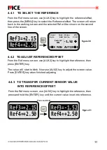
Page 32: ...nce offset values These values are adjustable through the reference menu At any given time only one of the four references offsets can be selected as the current reference offset for the sensor From t...

Page 33: ...se key to highlight the reference then AUX2 press key ENTER The value will start to blink Now use key to adjust the screen value AUX2 Press key when finished adjusting ENTER Ref3 2 15 Ref4 2 50 Laser...

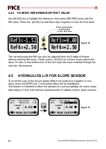
Page 34: ...ugh the menu for this purpose Ref3 0 00 Ref4 2 50 Ref3 1 52 Ref4 2 50 Press up and down keys together to zero Ref value 4 5 HYDRAULICS L R FOR SLOPE SENSOR To invert the sign of the current grade offs...

Page 35: ...lect the Advanced Settings then press AUX2 ENTER key to bring up the advanced settings In the Advanced Settings submenu use key to scroll down to the Aux AUX2 Keys option Press key to toggle between A...

Page 36: ...Copy to Right Exit Laser Sensor Left General Settings Calibration Parameter Settings Copy to Right Exit Laser Sensor Left Dead Band 10mm Response Off Prop Range 127mm Ctrl Range Off mm Measure Mode A...

Page 37: ...Ctrl Range On 30 0 Exit Slope Sensor Left Dead Band 0 50 Response Off Prop Range 20 0 Ctrl Range On 30 0 Exit Slope Sensor Left Dead Band 0 50 Response Off Prop Range 20 0 Ctrl Range On 30 0 Exit Slop...

Page 38: ...DEADBAND RANGE Laser sensor P Laser sensor mm 0 5 mm to 10 mm 4 mm 20 mm 29 mm Slope sensor Sonic tracer sensor GPS sensor 2 mm to 10 mm 0 2 to 2 8 mm Note deadband setting is not available when resp...

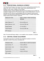
Page 39: ...de the deadband beginning of the Proportional range and the Max hydraulic out put is reached when the sensor reading deviates from the Target by by an amount equal to or greater than the selected Prop...

Page 40: ...lly becomes elative o revert back to absolute access sensor r T settings menu select measure mode and press ABS is then shown in ENTER the square brackets Note On power down the DUO retains the previo...

Page 41: ...y of 0 01 5 The sensor is approximately level with the blade Checks should be done a new job to ensure that calibration is before starting maintained his involves physically leveling the blade using a...

Page 42: ...ration of the sensor press from the working menu MENU key Select to which the sensor the side is installed then select Sensor Settings F the ollow configuration steps described below Left Side Hydraul...

Page 43: ...AUX2 ENTER Set Default Slope Side Right Side Mini Stick Aux Keys Reference Ref Edit Unlocked Hydraulic Unlocked Auto Man Unlocked Set Default Slope Side Left Side Mini Stick Aux Keys Reference Ref Ed...

Page 44: ...NESS Us key to highlight the Brightness setting and then press key e AUX2 ENTER to bring up the current brightness settings for LCD The setting will start to blink Using key adjust the brightness betw...

Page 45: ...the LED Brightness to suit your eyes and cabin light AUX2 conditions Press key when done ENTER Using to highlight the LED rightness setting and then press AUX2 key B ENTER B key to show the current L...

Page 46: ...e mast is connected on either side of the DUO a message saying No no 2 MAST will be displayed 5 5 1 MAST WORKING SCREEN 5 5 2 MAST FUNCTION KEYS Current mast position Mast measurement Unconnected mast...

Page 47: ...fr m the mast working menu reference the REF o then select a reference slot After selecting a reference slot press key and the selection will flash ENTER Use key to select and set a new reference poin...

Page 48: ...ss and hold press once to increase or decrease the mast height 2 U REF button o pon the release of the the mast will move up or down t a value equal to RO1 offset T multiple of RO1 o adjust the mast h...

Page 49: ...lected Exit back to the mast working screen 5 5 4 2 USING OPTIONAL JOYSTICK Set Default Slope Side None Prop Mini Stick Mast Aux Keys Reference Ref Edit Unlocked Hydraulic Unlocked Auto Man Unlocked S...

Page 50: ...st height by RO1 offset press and hold L R button then tilt the joystick towards UP LEFT or DOWN LEFT position and back to neutral position multiple times while holding the L R button In neutral posit...

Page 51: ...land grading The GN S sensor is always shown on the left side of the working screen All the S information and settings related to GN S are shown in the typical example S below with the GN S in a fixed...

Page 52: ...e points A B to define accurately the orientation of slope targets Set up a new job Please drive to Ref Point A then press Enter Set up a new job Setting Ref Point A Continue with these same steps to...

Page 53: ...de Accessory Sensors LCD LED Settings Advanced Settings Exit Aux Hydraulic Machine Standard H Control Standard Slope Sensor GNSS Speed 3 0km h Show ULS P Reading Y Exit Aux Hydraulic Machine Standard...

Page 54: ...ress using AUX2 key P ENTER key to exit Select YES if you want to proceed with system default using AUX2 keys Press key to execute ENTER Screen will return to the menu after displaying System Advanced...

Page 55: ...e of joystick connected to the system From the main menu screen use to scroll down to joystick option AUX2 key and press key the correct type of joystick keep ing the until is shown ENTER Left Side Ri...

Page 56: ...located on the same axis on the joystick handle ii Simple ON OFF Hydraulic activation is not proportional to handle position activation iii Includes 3 buttons on top for switching between Auto and Ma...

Page 57: ...he connected joystick will override this button If no joystick is being used select Side Mini Stick the default option h Mast Offset Stick Note Only cable with bare wires is provided The switches are...

Page 58: ...reading 4 Switch to AUTO hydraulic control to begin The following example is provided to help demonstrate how setting reference offsets zeroing and mounting would be done in practice This example invo...

Page 59: ...range during normal grading operations Option 2 should only be used in cases where the desired offset is less than 80 120 mm so that the tracer is kept within its operating range of 250 450 mm when i...

Page 60: ...A MOBILE AUTOMATION AUSTRALIA PTY LTD ABN 866 279 713 68 90 Willandra Drive Epping Victoria Australia 3076 Ph 61 3 9357 0055 Email aumoba moba de www moba automation com au A U S T R A L I A P T Y L T...

Reviews: