background image

- 9 - 


Warranty  


The M.Becker company  offers a warranty period of 12 months from 
date of delivery  on the power generating systems MB7500-110 and all 
components for fault-free operation and flawless material quality under 
normal storage and operating conditions. This warranty does not extend 
to maintenance or service work, no matter what nature. The warranty is 
only valid for the first purchaser and does not apply to products or 
single components, which have been inappropriately used or on which 
alterations have been carried out. Any warranty claim expires if the 
operation of MB7500-110 was not for its intended purpose or under 
abnormal conditions and repairs or alterations have been carried out, 
which were unauthorised by the M.Becker company. 
 
The warranty liability is limited to repairs or the replacement of a 
product, which has been send to the M.Becker company within the 
warranty period. It is a prerequisite that the M.Becker company 
acknowledges the device as faulty, and the fault did not come from 
inappropriate use or alterations to the device, application for which the 
device was not intended or from abnormal operation.  
 
The above warranty regulations are valid exclusively and take the place 
of all other contractual or legal warranty obligations, including, but not 
limited to, the legal warranty regulations governing marketability, 
appropriate use and expediency for a particular use. 
 
The M.Becker company does not take any liability for damages that are 
not directly related to the application of the device, where they 
immediate or indirect, independent of it, whether they came from 
legitimate or illegitimate or any other actions.  
 
Warranty and liability claims in cases of damage to persons or property 
shall be excluded, if they are attributable to one or more of the 
following causes: 


Use of the MB7500-110 other than for the intended purpose; 


Incorrect assembly, installation, commissioning, operation and 
maintenance of the MB7500-110  


Operation of the MB7500-110 if the installations for safety purposes 
are defective or if the safety and protective measures are not installed 
or are not operational. 

Summary of Contents for MB7500-110

Page 1: ...MB7500 110 the Mobile Power Generating Systems for Motor Vehicles Operating Manual...

Page 2: ...M Becker Benzstra e 6 70839 Gerlingen Telefon 07156 28202 Telefax 07156 17 00 09 email m becker mobie de http www mobie de Edition 11 2010 The right to technical modifications is reserved...

Page 3: ...e operation and reduces the risk of electric shock No component of the system except the generator shall be serviced by the user No component shall be opened for reasons of inspection unless this is e...

Page 4: ...n HD 60364 4 41 20070100 DIN 14687 2007 02 firefighting systems Integral power generating systems 12 kVA used in fire brigade vehicles DIN IEC 61326 2 4 VDE 0843 20 2 4 2010 05 2010 05 Electrical equi...

Page 5: ...system is operational Insulation Monitoring 17 2 4 1 Insulation Monitoring 18 2 5 COMMISSIONING 19 2 6 COMMISSIONING OF MB7500 WITH MB6001F 19 2 6 1 Commissioning of MB7500 with Low cost master switch...

Page 6: ...nic which is incorporated in a metal enclosure Any other or surpassing application is not deemed to be the purpose for which it is intended The M Becker company is not liable for damages sustained as...

Page 7: ...o the state of the art and recognised safety engineering rules nevertheless when it is being applied hazards may occur to the life and limb of the user or third parties or there may be adverse effects...

Page 8: ...ensure if the relevant precautions are not taken This symbol indicates an immediate danger to life and health of persons Failure to comply with this warning means that death serious physical injury or...

Page 9: ...he device as faulty and the fault did not come from inappropriate use or alterations to the device application for which the device was not intended or from abnormal operation The above warranty regul...

Page 10: ...missioning operation and maintenance of the MB7500 110 Unauthorised structural alterations to the MB7500 110 Failure to comply with the technical data Inappropriate repairs and the use of replacement...

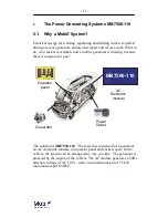
Page 11: ...s missing because there is no space for one The solution is MB7500 110 The system is composed of a generator an AC electronic module an operator panel and sockets each In the vehicle the system can be...

Page 12: ...put frequency to 50 Hz The electronic modules MB7500 110AC have no controls and displays All operational messages and fault signals are indicated on the operator panel MB6001ST 110 The output lines ha...

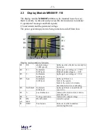
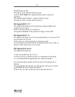
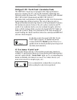
Page 13: ...fault alarm LED red lights up if overvoltage is 150V blinks if undervoltage is 90V H3 I fault alarm LED red lights up if overvoltage is 90 A H5 Syst fault alarm LED red lights up if there is a fault...

Page 14: ...load current drawn is in excess of 75A for more than one second If this is the case the operator has to reduce the load As a precaution the system will be disconnected after one second to protect it f...

Page 15: ...socket the signal LED H5 ligths up and or the system is going to be disconnected The fault message gets stored Pushing the master on off switch on the control panel MB6001F will reset the fault signal...

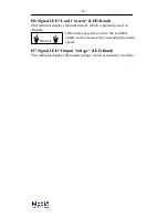
Page 16: ...he load current which is presently used in Ampere If the motor speed is too low the available output can be increased by increasing the motor speed H7 Signal LED Output Voltage LED Band This indicator...

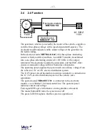
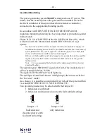
Page 17: ...sinusoidal voltage with low harmonic components The operating panel supplies the system with an auxiliary voltage from the vehicle s 12V or 24V electric distribution system The 110V power circuit has...

Page 18: ...s or to earth This device shall initiate an audible and or visual signal If there are both audible and visual signals it is permissible for the audible signal to be cancelled but the visual alarm shal...

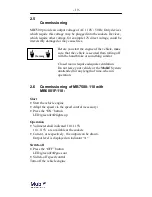
Page 19: ...losed rooms require adequate ventilation Do not leave your vehicle or the MobiE System unattended for any length of time when in operation 2 6 Commissioning of MB7500 110 with MB6001F 110 Start Start...

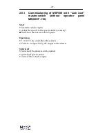
Page 20: ...Start the vehicle engine Adapt the speed via the speed control accessory Switch on the master switch option Operation 110 115V are available at the sockets Current or respectively the output can be dr...

Page 21: ...for the fault indications on the operator panel MB6001F 110 If the following notes do not achieve the desired success ask a qualified and electrically skilled person for their advice Never endeavour t...

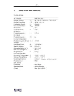
Page 22: ...I 75 A Protection against Excess Temperature T ja Protection against Over Voltage U 150 V Insulation Fault RAN 23 kOhm Supply Voltage US 12 24 V Operating Range of Us 9 6 36 V Power Consumption 80 VA...

Page 23: ...70 C 25 70 C Mounting Position any position Weight of the Electronic Module G 0 6 kg Protection acc DIN 40050 IP4x IP4x Enclosure cast Aluminium Measurements 125x80x57mm Colour light grey Generator MB...

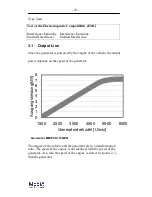
Page 24: ...f the vehicle the output power depends on the speed of the generator Generator MB7500 110GEN The engine of the vehicle and the generator are in a transformation ratio The speed of the engine is not id...

Page 25: ...the belts which are required to drive the generator The belts have to be adequately tightened When a replacement is required it is important that only high performance and industrial quality belts ar...

Page 26: ...tion has to be disconnected Therefore the hook switch S1 must be open The terminals U V W L1 and L2 must be by passed The test hast o be done between U V W L1 L2 and PE After the test the hook switch...

Page 27: ...27 3 3 Wiring Diagrams 3 3 1 AC Modul MB7500 110 30 0 7 0 200 0 25 0 350 0 330 0 300 0 140 0 15 0 mm M6 approx 47mm 190 mm 340 400 140 ground bolt...

Page 28: ...28 3 3 2 Operator panel MB6001F 110 depth 57 mm...

Page 29: ...29 3 3 3 Generator MB7500 110 GEN Measurements in mm...

Page 30: ...30 3 3 4 Connectiondiagram...

Page 31: ...31 3 4 Order Details Article Typ Article number Electronic Module 110 V 50 Hz MB7500 110 B7011 Operator panel 110V MB6001F 110 B2111F Generator 7 5 kW MB7500GEN B7111...

Page 32: ...m becker mobie de http www mobie de Branches Hartmut Kn pp Wilhelm Heinrich Strasse 27 61250 Usingen Wilhelmsdorf Tel 06081 68 68 81 Fax 06081 58 38 84 email h knoepp mobie de Fahrzeugtechnik Bernd Be...

Reviews: