background image

1. Attaching a Tool

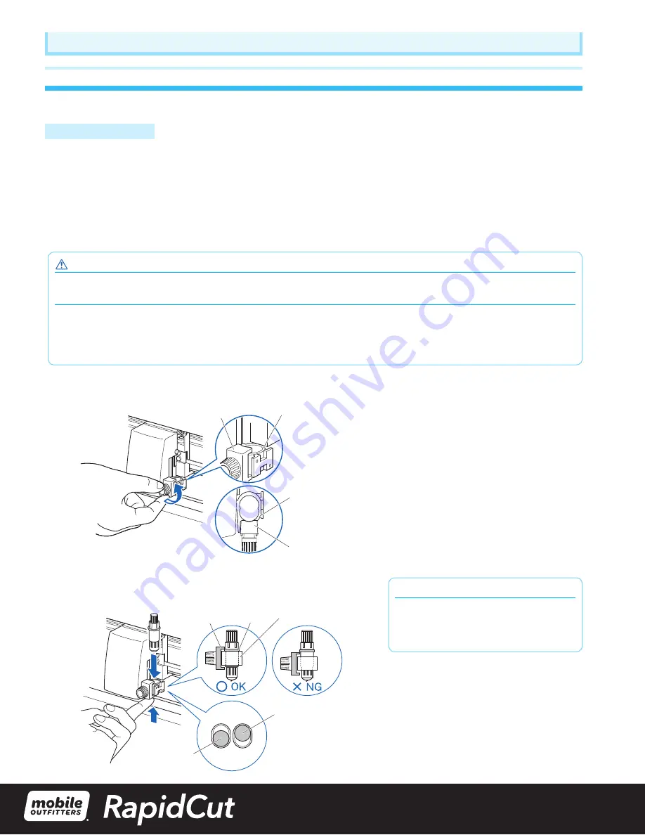
Attach a tool (cutter plunger, plotter pen) to the plotter.

Attaching a Tool

When mounting the tool in the tool holder, please note the following.

3XVKWKHWRRODOOWKHZD\LQWRWKHKROGHUXQWLOLWVÁDQJHFRQWDFWVWKHXSSHUSDUWRIWKHKROGHUDQGWKHQWLJKWHQWKHVFUHZ

ÀUPO\

7RSUHYHQWLQMXU\DYRLGDEVROXWHO\WRXFKLQJWKHWRROLPPHGLDWHO\DIWHUWKHFXWWLQJSORWWHULVWXUQHGRQRUZKHQHYHUWKHWRRO

is moving.

)RUGHWDLOVVHH´$WWDFKLQJD7RROµRQLQ8VHU·V0DQXDO 

It is explained here using cutter plunger as an example.

 CAUTION

:KHQSXVKLQJWKHWRROKROGHUZLWK\RXUÀQJHUVWKHEODGHWLSPD\EHSURWUXGLQJ7DNHFDUHQRWWRFXW\RXUÀQJHUV

Supplement

 When using with half cutting and plotter pen, set the seal in Tool Holder 1 (backward), and when using cutting out (perforated cut), set

the seal in Tool Holder 2 (forward).

 Cutting out means that the media is cut out completely.

+DOIFXWWLQJPHDQVWKDWRQO\WKHPDUNLQJÀOPLVFXWRXWOHDYLQJWKHEDFNLQJVKHHWXQFXW

1

  Loosen the tool holder screw.

Tool holder

Bracket to hold tool

Bracket to hold tool

Tool holder

Top

Supplement

When using with half cutting and plotter pen, 

set the seal in Tool Holder 1 (backward), and 

when using cutting out (perforated cut), set the 

seal in Tool Holder 2 (forward).

2

 :KLOHSXVKLQJXSWKHWRROKROGHUSXVKXQWLOLWVÁDQJHFRPSOHWHO\WRXFKHV

the upper part of the holder.

Flange

Bracket to 

hold tool

Tool holder 1 

(Backward : Half cutting/Plotting Pen)

Tool holder 2 

(Forward : Using 

cutting)

Tool holder

Setting up the Plotter main unit

Summary of Contents for RapidCut 2.0

Page 1: ...ies Cables USB Tablet Power Cutter Power 2 0 Tape Measure Tweezers Plug Adapters Replacement Blade Safety Instructional Manual Your new RapidCut 2 0 system includes PIN Number Serial Number RapidCut S...

Page 2: ...Table of Contents 1 Unboxing Plugging in Powering up Connecting to WiFi New Portal Log In Packing a Return 2 3 4 5 Pg 13 18 Safety Guidelines Pg 19 24 Cutting Plotter Setup Manual...

Page 3: ...ors they will be used to packaging if you are returning a system See part 5 for returns You are now able to remove the cutting system from the box Lift the cutter from the machine DO NOT lift from the...

Page 4: ...pidCut is removed from the box Remove each end protector by pulling them one at a time away from the machine 1 1 Remove cardboard packaging by gently pulling it straight out Remove Cutting blade prote...

Page 5: ...ing in Powering up Once the RapidCut system is unpacked rotate the tablet perpendicular to the cutting machine as shown below This exposes the USB port for connecting the tablet to the cutting machine...

Page 6: ...Plug the USB cable into the USB 3 0 port here Once the USB cable is plugged in rotate the tablet to be parallel with the cutting machine as shown below 2 1...

Page 7: ...power into your wall outlet If necessary use the included plug adapters Once plugged in the green light on the top right corner of the tablet should light If the green light does not come on press the...

Page 8: ...will be prompted to confirm this action Select Yes Once logged off swipe up on the screen showing time and date This will reveal the user account screen Tap RapidCut User DO NOT LOG IN Once the user...

Page 9: ...er password Once WiFi is connected Tap on the RapidCut User password field enter password 1111 Once logged in Tap on Open RapidCut Enter your location 4 digit pin number RAPIDCUT Networks Airplane mod...

Page 10: ...RapidCut2 moutfitters com Once the portal has loaded enter your Email and Password Your RapidCut portal password is emailed to the account email prior to the delivery of the RapidCut system and more...

Page 11: ...nder the rollers do not force 5 6 Gently lift up on the blade holder and slide the foam cube under the blade Turn off cutting machine unplug the usb and power cables from the cutter 1 You will re use...

Page 12: ...er machine DO NOT add any other items or warranty returns in the box Please pack them separately Use bubble wrap and or packing paper to fill out the partition Tape the box securely and apply included...

Page 13: ...TO ENSURE SAFE AND CORRECT USE RapidCut u m jJ ss wmm SSfJJ pm fJJ jJ mmm Tl wss m 1 1111 RapidCut...

Page 14: ...ed below Be sure you understand the difference between each of the categories DANGER This category provides information that if ignored is highly likely to cause fatal or serious injury to the operato...

Page 15: ...ddenly start moving when data is received Such action may cause human injury Do not disassemble repair or remodel the cutting plotter Such action may cause electrical shock or a fire hazard due to cur...

Page 16: ...ec vendor to request repair Never try to perform repair yourself Repair work by inexperi enced personnel is extremely dangerous Do not allow dust or metallic matter to adhere to the power plug A dirty...

Page 17: ...lectrical noise Such location may impair the performance of the cutting plotter When disconnecting the power cord or an interface cable do not pull on the cord cable Such action will damage the cord c...

Page 18: ...oximity of such a fight source may cause the sensor to malfunction and prevent proper size detection of the media When using the cutter be sure not to extend it s blade more than necessary An overly e...

Page 19: ...th the instruction manual may cause harmful interference to radio communications Operation of this equipment in a residential area is likely to cause harmful interference in which case the user will b...

Page 20: ...W 0RELOH 2XWILWWHUV YHQGRU LI RX ILQG DQ XQFOHDU RU HUURQHRXV LQIRUPDWLRQ RU ZLVK WR PDNH RWKHU comments or suggestions Notwithstanding the stipulations in the preceding paragraph 0RELOH 2XWILWWHUV Co...

Page 21: ...our website When there are virus detection program or system resident program terminate them beforehand Upon installation be sure to log into Windows using an account with administrator privileges on...

Page 22: ...When using with half cutting and plotter pen set the seal in Tool Holder 1 backward and when using cutting out perforated cut set the seal in Tool Holder 2 forward Cutting out means that the media is...

Page 23: ...VHH GMXVW WKH 3XVK 5ROOHU Both roll media and sheet media can be used with the 5DSLG XW Load the media according to the instructions given for each type Use the grit roller on the right side of the me...

Page 24: ...lers about the position of the push rollers The push rollers push down on either side of the media Use the grit roller position guide to make sure the push rollers are set on top of the grit rollers P...

Page 25: ...n the proper grit roller Make sure everything is set correctly For minimum width media Make sure that all push rollers are on the long right grit roller Use the left side of the grit roller as a start...

Reviews: