Checking the Transmitter Operation and Flight Controls
17.
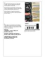
Load 8 x AA size alkaline batteries into the
transmitter.
1.
2.
3.
4. 5.
6.
7.
8.
9.
10.
11.
18.
Transmitter control layout for
Mode 1
radio:
1. Rudder
Control*
2. Elevator
Control
3.
Rudder Trim Lever*
4.
Elevator Trim Lever
5.
Throttle Trim Lever
6. Aileron
Control
7. Throttle
Control
8.
Aileron Trim Lever
9. Battery
Indicator
10. Servo Reverse Switches
11. On/Off Power Switch
18.
Transmitter control layout for
Mode 2
radio:
1. Rudder
Control*
2. Throttle
Control
3.
Rudder Trim Lever*
4.
Throttle Trim Lever
5.
Elevator Trim Lever
6. Aileron
Control
7. Elevator
Control
8.
Aileron Trim Lever
9. Battery
Indicator
10. Servo Reverse Switches
11. On/Off Power Switch
19.
Turn on the transmitter
making sure that the
throttle stick is pulled all the way back
. The
red LED will glow red and the battery indicator
needle should move into the silver area of the
indicator.
IMPORTANT:
1.
Replace the batteries if the indicator
needle does not move past the red area
2.
DO NOT fly the model if the indicator
needle is in the red area.
*Not used or required for this model

