Page 6
Page 15
l
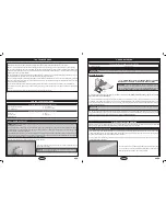
During the covering process, sometimes color may smear slightly from the seams. If you see any smeared colors on the covering
material, they can be quickly removed by simply wiping them off with a paper towel and a small amount of acetone.
l
Make sure to test-fit the parts together before applying glue. This will ensure that the parts fit properly before gluing them together.
l
When gluing anything that has a smooth surface, it's important to lightly roughen the gluing surfaces with 220 grit sandpaper. This
will allow the glue to stick better. Also, never glue directly to the covering material. Always remove the covering material from the gluing
surfaces prior to gluing the parts together.
l
When cutting away the covering material from the gluing surfaces, be careful to cut only through the covering material. Try not to cut
down into the balsa structure because that can compromise the integrity of the airframe.
l
We do not suggest storing your aircraft in an extremely hot environment (like the back of your car in direct sunlight) for any length of
time. The extreme heat could cause the covering material to wrinkle or sag and possibly damage the fragile components of the radio
control system and/or LiPO battery.
l
Epoxy can be cleaned up before it dries using rubbing alcohol, and C/A can be cleaned up before it dries using C/A Debonder.
l
To prevent current loss, make sure to use high-quality connectors between the battery and the ESC, and between the ESC and
the motor.
l
Insulate solder joints with heat-shrink tubing to prevent short circuits and corrosion.
TiPS FroM The ProS
q
Thin C/A
q
C/A Debonder
q
Modeling Knife
q
(1) Wing with Hatch Cover
q
(1) Right Elevon
q
(1) Left Elevon
q
(6) C/A-Style Hinges
q
T-Pins
q
Paper Towels
CoNTrol SurFACe hiNGiNG
you'll Need The FolloWiNG PArTS FroM The KiT:
you'll Need The FolloWiNG ToolS ANd SuPPlieS:
STeP 1: hiNGiNG The eleVoNS
IMPORTANT
The hinges are NOT glued into place from the factory, they are simply slid into place dry for shipping purposes. You
must glue them into place.
C/A-style hinges are used to hinge the control surfaces. These hinges are designed to be glued into place using thin C/A. Do not
glue these hinges into place using any other type of glue, such as thick C/A or epoxy. Use of any adhesive other than thin C/A could
result in failure of the hinges during flight.
For flutter-free control surfaces and crisp control response, it is imperative that the hinges be glued in properly. This is achieved by
having a tight hinge gap [no more than 1/32" (.7mm) wide] and using plenty of thin C/A glue. Poor hinge installation can lead to control
surface flutter which can result in a catastrophic failure of the airframe.
PRO TIP
The T-Pins will keep the hinges centred and square to the hinge
line while you are hinging the elevon.
q
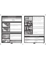
Working with one elevon for now, push two T-Pins through the centre of
each of the three hinges.
q
Remove the two elevons and the six C/A-style hinges from the wing.
C/G ANd bAlANCiNG
Balance poinT (c/g):
IMPORTANT
It is critical that your aircraft be balanced correctly. Incorrectly balancing your aircraft can cause your aircraft to lose
control and crash!
+
Once you have flown and become familiar with the flight characteristics of the aircraft, the C/G can be moved fore or aft to change
the flight performance. Moving the C/G back will cause the aircraft to be more responsive and aerobatic, but less stable. Moving the C/G
forward will cause the aircraft to be more stable, but less responsive.
See warning above.
q
Apply two short pieces of masking tape onto the
ToP
of the aircraft,
4-1/4" (108mm) behind the leading edge, measured at the
sides of the of the radio compartment.
q
Turn the aircraft over (upside down) and place your fingers on the masking tape, then carefully lift the aircraft. If the nose of the
aircraft falls, the aircraft is nose heavy. To correct this, move the flight battery back far enough to bring the aircraft into balance. If the
tail of the aircraft falls, the aircraft is tail heavy. To correct this, move the flight battery and/or receiver and ESC forward far enough to
bring the aircraft into balance.
IMPORTANT
When balanced correctly, the aircraft should sit level or slightly nose down when you lift it up with your fingers at
the C/G location.
l
4-1/4" (108MM) BAck FROM ThE lEADing EDgE OF ThE Wing,
MeASured AT The SideS oF The rAdio CoMPArTMeNT.
warning
This is the recommended C/G location for test-flying. After you
become familiar with the flying characteristics of the aircraft, you can move
the C/G forward or backward to suit your flying style.
We suggest moving the
c/g in 1/8" (3mm) increments until you are satisfied with the result.
q
Straight Edge Ruler
q
Masking Tape
you'll Need The FolloWiNG ToolS ANd SuPPlieS:
AirCrAFT SeTuP iNForMATioN
Before adjusting the control throws and flying your new aircraft, there are some points about the aircraft's setup that you should be aware
of. We strongly suggest following these suggestions to get the most enjoyment out of your aircraft.
Because of the high speed that the aircraft flies at, we suggest that the elevon hinge gaps be sealed. Failure to do this can lead to control
surface flutter, which can cause your aircraft to crash. Sealing the hinge gaps will also provide crisper control response and allow the
aircraft to track straighter and fly truer, making trimming much easier.
The hinge gaps can be sealed using heat-shrink covering material or clear vinyl tape. To seal the hinge gaps using heat-shrink covering
material, follow these procedures:
STeP 1: SeAliNG The hiNGe GAPS
q
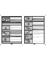
Cut a piece of covering material 3/8" (10mm) wide and 8" (203mm) long.
q
Fold the length of covering material in half lengthwise so that there is a
sharp crease down the middle of the covering material.
4-1/4" (108mm)


