36
Combustion models
• For receiver power supply, a battery/rechargeable battery box with four mignon batteries/rechargeable batteries or a
rechargeable battery pack with 5 cells is required for connection to the ”BATT” connection of the receiver.
• Adjust the throttle/brake servo linkage so that the carburettor linkage is in its central position and the brake is not
active yet. Observe the operating instructions for motor and model.
• The carburettor throttle valve (throttle plug) should be almost close (idle position).
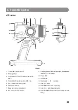
• When the throttle/brake lever (figure 1, item 6) at the transmitter is pulled towards the handle, the carburettor must
be opened all the way (full throttle position).
• If the throttle servo moves in the wrong direction, toggle the throttle/brake reverse switch (figure 1, item 8) to switch
the servo direction.
• By conducting practical tests, you can now determine the point of the rudder horn at which the you must attach the
carburettor linkage to achieve the best possible opening of the carburettor.
• When pushing the throttle/brake lever (figure 1, item 6) all the way away from the handle, the vehicle’s brake must
engage. An adjustment screw at the carburettor prevents the carburettor from closing completely. This way the
engine will not stall when the brakes are applied (idle position).
• Before you start the motor for the first time, set the appropriate function for the throttle plug at the carburettor using
the springs and adjustment rings at the linkages.
• Using the throttle/brake trim control (figure 1, item 4), you can fine-tune the idle run of the motor. Adjust the servo
linkage at the carburettor until the trim control is at the exact centre again at best idling.
Setting the steering servo
• Put the trim control for the steering trim (figure 1, item 3) in the central position at the transmitter.
• The wheel (figure 1, item 2) for the steering servo is automatically kept in its central position by spring force.
• Please check that the servo lever is mounted correctly in the neutral position. Only if the steering linkage can move
the same distance in either direction, the model can drive curves of the same size in either direction.
• Check that the wheels deflect to the left when you turn the wheel at the transmitter (figure 1, item 2) to the left. If this
is not the case, toggle the servo direction using the steering servo reverse switch (figure 1, item 12).
• Adjust the steering linkage until, e.g., the wheels of a model car are straight (a slight toe-in is sensible!).
• During the first drive, adjust the steering trim control (figure 1, item 3) until your model drives straight.
• Then adjust the steering linkage in the respective direction until the model drives straight and the steering trim
control (figure 1, item 3) is in the central position again. This will give you the full trimming path again later.

