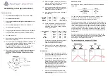
Connections and accessories
Important information!
Do not operate the gyro before you have read the following chapters completely and know what
has to be observed during installation and operation. This is the only way to prevent
malfunctions or even damage.
The gyro is connected to the receiver output for the tail servo. The tail servo itself is connected to the gyro
system directly. This means that the gyro is connected between the receiver and the tail servo. In addition,
the gyro is connected to another receiver output which is used later to set the sensitivity.
1 Gyro
2 Receiver connection for gyro sensitivity
3 Receiver connection for the tail servo
4 Connection plug for the tail servo
5 Double-sided adhesive tape to attach the gyro
6 Miniature screwdriver
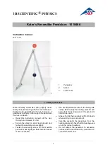
Installation of the gyro
When installing the gyro, ensure that you select a place of installation where the gyro is well protected from
vibrations and heat variations. In many cases, the manufacturers of model helicopters predefine the exact
place of installation for the gyro.
If this is not the case with your model, select a place of
installation which is close to the main rotor shaft (7). The
installation platform (8) where you install the gyro must
be in a 90° angle to the main rotor shaft. Only use the
provided double-sided adhesive foam (9) for installation.
The stabilising axle (10) of the gyro runs parallel to the
main rotor shaft if installed properly. The settings regulator
and the slide switches are easily accessible from the top.
The cables connected to the gyro must be laid so that
they cannot get in contact with moving parts or be worn
by sharp edges.
Illustration 2 shows the correct installation of the gyro in a small electric helicopter with a rotor diameter
of approx. 720 mm.
Installation of the tail servo
The installation of the tail servo (11) and the adjustment
of the tail rotor are normally set out precisely in the
instructions of the model helicopter.
Important information!
In order for the gyro to work most effectively,
the servo lever (12) and the linkage rod (13)
must be in a 90° angle to one another (neu-
tral position).
The distance (A) depends on the model size and is
normally stated in the documents of the model helicopter.
Ensure an absolutely smooth and free-of-play control of
the tail rotor. The gyro will only work ideally if even small
servo throws cause a control response on the model.
Connecting the gyro
Connect the gyro to the 3-pole connecting cable (3) on
the receiver output for the tail servo.
Black = negative
Red = positive
White = pulse
Connect the 1-pin adjustment input (yellow = pulse) of
the gyro (2) with a free channel of the receiver which is
controlled with a slide control via the transmitter.
What connections have to be used on the receiver
depends on the remote control and is described in the
respective documentation.
The tail rotor servo (11) is connected directly to the connection plug for the tail servo (4). Make sure the
polarity of the servo plug (14) is correct.
Operating the gyro
Before you operate the gyro for the first time, any tail mixers programmed in the transmitter (e.g. revolution
mixing or gyro suppression mixer) have to be deactivated.
The gyro is not equipped with a power switch. Power supply is provided by the receiver via the 3-pin plug
connection. As soon as the receiver is switched on, the gyro is in operation.
The tail function control stick and the corresponding trim must be in centre position before you operate the
receiver and the gyro. The tail rotor should then be aligned so that the helicopter has no tendency to turn
to the side (factory settings) when hovering.
Head-Lock-Gyro "MC-800"
Item no. 20 64 88
Intended use
This gyro system is a compact stabilising system which detects position changes thanks to a Piezo sensor.
Via integrated electronics a downstream servo is controlled to oppose the change of position. Due to the
compact construction and the low weight, this system is also ideal for smaller electrically driven model
helicopters.
The gyro can be operated in normal or AVCS mode (angular vector control system).
In normal mode, the downstream servo is only corrected as long as the rotary movement of the model is
identified by the gyro.
In AVCS mode (head-lock mode), the downstream servo is corrected only as long as the original starting
position (angular position) of the gyro has been reached again.
When the tail is controlled directly, the gyro effect is automatically suppressed and the model responds to
the control commands of the transmitter. After turning, the servo assumes neutral position again and the
gyro takes over the stabilisation of the tail again.
The gyro effect is adjustable. It can be adjusted or switched via the transmitter.
Safety information
The guarantee/warranty will be void if damage is incurred resulting from non-compliance
with the operating instructions. We assume no liability for any consequential damage!
We do not assume any liability for damage to property or personal injury caused by
improper use or the failure to observe the safety instructions! In such cases the
warranty/guarantee is voided.
Normal wear and tear and accident and crash damages are also excluded from the guarantee
and warranty.
Dear Customer,
these safety instructions are not only for the protection of the product but also for your own
safety and the safety of others. This is why you should read this section very carefully before
using the product!
a) General information
• The unauthorized conversion and/or modification of the product is inadmissible for safety and approval
reasons (CE).
• The product is not a toy and should be kept out of reach of children under 14 years of age.
• The product must not get damp or wet.
• Do not leave packaging material lying around unattended. It can become a dangerous toy for children.
b) Before operation
• Install the gyro in your model so that oscillation, vibrations and agitation can be ruled out as effectively
as possible.
• Check the functional reliability of your model and of the remote control system. When doing so, make
sure there is no visible damage such as defective plug connections or damaged cables. All moving parts
of the model must run smoothly, but should not have any play in their bearings.
• Before each operation, control the settings of the trims on the transmitter for the different steering
directions and, if necessary, adjust them.
• Always switch on the transmitter first. Then the receiver with the gyro connected to it may be switched
on. Otherwise the model or the servos might show unpredictable responses.
• Before every use, check the gyro for correct function and make sure it sits properly in the model. The
model cannot be controlled if the gyro is loose or disconnected.
c) During or after operation
• Do not take any risks! Your own safety and that of your surroundings depend on your responsible
handling of the model.
• Improper operation can cause serious damage to people and property! Therefore, during operation,
make sure there is sufficient safe distance to persons, animals or objects.
• Select a suitable area to operate your model.
• Do not steer your model towards spectators or towards yourself.
• Always leave the remote control (transmitter) turned on as long as the model is in operation. Always
switch off your model first before switching off the remote control.
• In case of a fault or a malfunction, solve the problem before using the model again.
• Do not expose your model, the gyro and the remote control to direct sunlight or excessive heat over a
longer period of time.
MC 800
DELAY
LIMIT
OFF
ON
NOR
REV
DIR
DS
0
25
50
75
100
60
80
100
120
140
GYRO
AVCS
-
1
2
3
6
5
4
Figure 2
SER
VO
A
12
13
11
Figure 3
MC 800
DELAY
LIMIT
OFF
ON
NOR
REV
DIR
DS
0
25
50
75
100
60
80
100
120
140
GYRO
AVCS
-
14
11
SER
VO
1
2
3
4
Figure 4
Figure 1
Operating instructions
Version 02/09