28
a)
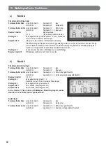
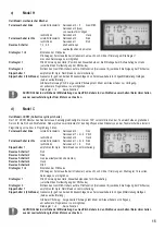
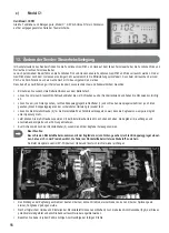
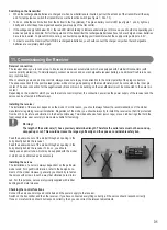
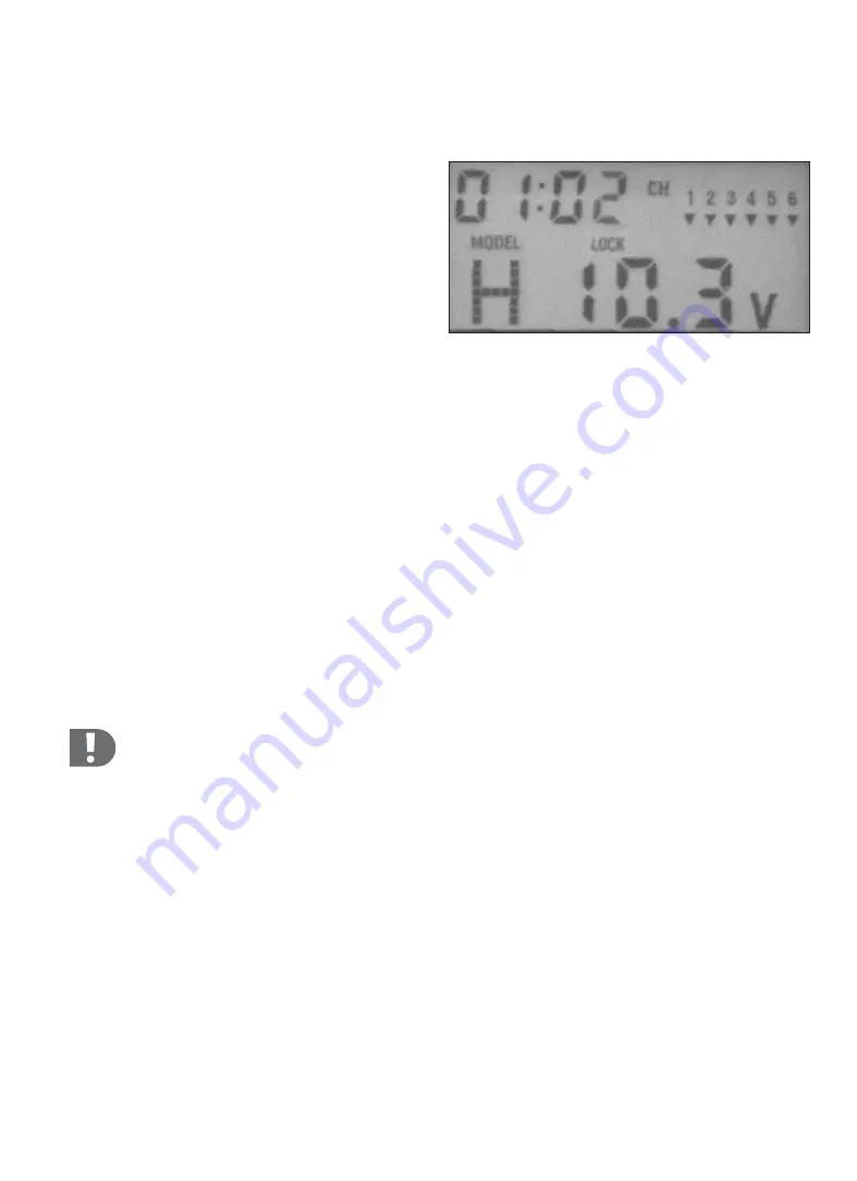
Display
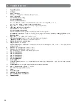
The most important information on the current settings is shown on the LC display.
Timer:
Shows the time since the transmitter was last switched on.
MODEL:
(A, V, H, C, C1)
The aircraft model preset is indicated.
CH:
Indication of the NOR (normal) or REV (reverse) position for the
function channels
LOCK:
This is displayed when the rotary controllers or the MODEL
pushbutton are locked.
V:
Voltage indication for the rechargeable batteries for the transmitter
b)
Controls
b)
Controls
Function channels
A function channel stands for the function assigned to a remote control lever or other control, such as gas/pitch, aileron, rudder, etc.
Under some circumstances, such functions may be performed by multiple servos simultaneously.
Depending on the aircraft model (MODEL A, V, H, C or C1), the same function channel may have different functions/effects on a particular
model.
By contrast, the direct assignment of a channel on a receiver to an individual servo (and thus the effect of that individual servo on the
model) is called a servo channel.
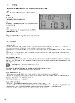
Undervoltage indicator (10)
In addition to the digital voltage indication on the display, the transmitter also has a red LED that starts blinking when voltage of 8.5 V is
fallen short of. So as not to lose control of the model, immediately end the flight operation and either charge or replace the batteries with
fully charged ones.
WARNING! Only rechargeable batteries may be used.
If the voltage drops below 7.6 V, the LC display goes out, and the LED continues to blink.
Now at the latest you must land the model and replace the batteries.
Toggle Switch Channel 5 (5)
The left toggle switch is assigned to Function Channel and Servo Channel 5 and has purely switching functions.
This can be used for any supplementary function desired, such as retracting and lowering retractable landing gear with model planes or
switching a gyro from normal mode into head-lock mode.
This Channel 5 does not have a reverse switch.
Toggle switch, dual-rate (7)
The right toggle switch in the front simultaneously has an effect on Function Channels 1, 2 and 4.
As a result, the effect of Functions 1,2 and 4 on the model are reduced from 100% (Position „0“) to 70% (Position „1“). This allows more
delicate control of the model, because the maximum mechanical lever travel remains available for the control system.
The dual-rate adjustment also has an effect on the influence exerted by the trim controls.

