31
Switching on the transmitter
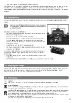
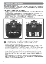
When the rechargeable batteries are charged or when new batteries are inserted, pull out the antenna of the transmitter all the way
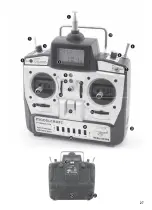
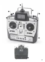
and, for test purposes, switch the transmitter on via the function switch (see figure 1, Pos. 13).
To do so, slide the control button from the bottom to the top (slanted). The green battery control LED (see figure 1, pos. 9) lights up
briefly and a short beep tone signals adequate power supply of the transmitter.
If the voltage supply falls below 8.5 V, the red LED starts blinking to indicate undervoltage. In this case, you should stop operating your
model as quickly as possible. For further operation of the transmitter the rechargeable batteries have to be recharged or new batteries
have to be inserted. To prevent this scenario, you should stop operating your transmitter when the supply voltage drops to 9.0 V.
In order to avoid the memory effect of NiCd rechargeable batteries, you should connect the charger only when the rechargeable
batteries are completely discharged.
Receiver connection
The receiver allows you to connect up to 6 servos and a receiver accumulator, which are equipped with Futaba/JR connectors (with
reverse polarity protection). To simultaneously connect six servos and one rechargeable receiver battery, an additional Y-cable is neces-
sary (not included).
When connecting servos and drive controls, always make sure to pay close attention to the correct polarity of the plug connectors.
The wrap connection for the positive lead (yellow, white or orange, depending on the manufacturer) must be connected to the inner pin
contact. The wrap connection for the negative lead (black or brown, depending on the manufacturer) must be connected to the outer pin
contact.
Depending on the model for which you use the remote control system, the connection as well as the power supply of the receiver and the
servos can be effected in different ways.
Installing the receiver
The installation of the receiver depends on the model. For this reason, you should always follow the recommendations of the model
manufacturer regarding receiver installation. Regardless of the model, you should always try to install the receiver so that it is protected
from dust, dirt, moisture and vibration in the best possible way. Two-sided adhesive foam (servo tape) or even rubber rings that hold the
foam-wrapped receiver securely in place are suitable for fastening.
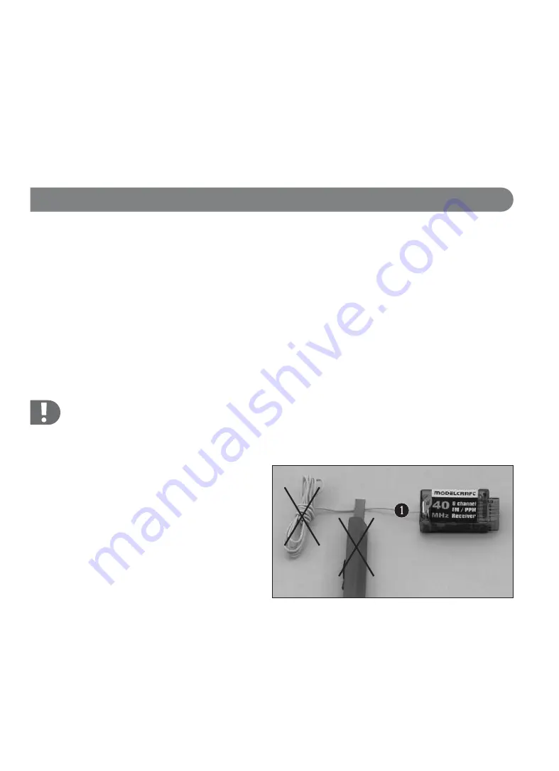
Warning!
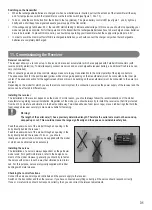
The length of the aerial wire (1) has a precisely determined length. Therefore the aerial wire must not be wound up,
wrapped up or cut. This would decrease the range significantly and thus pose a considerable safety risk.
Feed the aerial wire out of the model through an opening in the
body directly behind the receiver.
Feed the aerial wire out of the model through an opening in the
body directly behind the receiver. To do so, you should
ideally use an aerial tube, which may be supplied with the model
or which can be obtained as an accessory.
Installing the servos
The installation of a servo is always dependent on the particular
model used. For specific information, refer to the design docu-
ments of the model. However, generally you should try to fasten
the servos with screws in such a way that vibrations are minimi-
sed. For this purpose, servos are typically supplied with rubber
bushings with metal sleeves.
Checking the control functions
Connect the servos and/or speed controllers and the power supply to the receiver.
Switch on the transmitter and then the receiver. If you have connected everything correctly, all the servos should respond correctly.
If one or more functions should not respond correctly, then you can correct the relevant adjustments.
•
•
•
•
11. Commissioning the Receiver

