71
d) Switching on the Transmitter
Insert fully charged rechargeable batteries or new batteries or charge the rechargeable batteries in the transmitter
fully.
Check the position of the toggle switches. All switches should be in the forward or bottom positions. Now switch on the
transmitter using the on/off switch (see fig. 1, item 10).
First, you will hear three signal sounds in increasing pitch and the operating display with the currently set model
appears in the backlit display. The backlighting is deactivated automatically about 20 seconds after activation or the
last button operation. If no operating element ids operated within 60 s with the plant on, the plant will emit short signal
sounds.
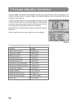
The operating display consists of the following elements:
1. Manufacturer display
2. HF-transfer type
3. Battery symbol
4. Operational charge display
5. Model type figure
6. Elevator/nod trimming display (in Mode II)*
7. Aileron/roll trimming display (in Mode II)*
8. Rudder/tail trimming display (in Mode II)*
9. Throttle/pitch trimming display (in Mode II)*
10. Model name display
11. Memory display
* Further information for mode setting can be found in the system setting menu in the menu item “Sticks mode”.
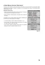
If one of the four toggle switches (see figure 1, item 4, 5, 18 and
19) is not in the front or bottom position, the transmitter will emit
warning sounds when activating and the corresponding note is
displayed.
In this case, the affected switch must be put in the front or bottom
position.
If the power supply is not sufficient for correct transmitter operation anymore, the battery icon will flash at
a voltage of less than 9.5 V. In this case, stop operation of your model as quickly as possible. To continue
operating the transmitter, recharge the batteries or insert new batteries.
If the voltage drops further, tow continually recurring alarm sounds sound at a voltage of less than 8.5 V. If
the voltage drops below 8,0 V, the system emits uninterrupted alarm sounds.
Figure 5
Figure 6
Summary of Contents for FS-T6
Page 9: ...9 9 Bedienelemente des Senders Vorderseite Bild 1 ...
Page 67: ...67 9 Transmitter Controls Front Figure 1 ...
Page 125: ...125 9 Éléments de commande de l émetteur Face avant Figure 1 ...
Page 183: ...183 9 Bedienelementen van de zender Voorkant Afbeelding 1 ...
Page 234: ...234 ...
Page 235: ...235 ...


