33
13. Verification of Steering and Driving Functions
Connect the servos or drive controls used in your model and the power supply to the receiver.
To prevent the model from driving off inadvertently while testing the steering and drive functions, place the
model chassis on a suitable basis (wooden block, etc.). The wheels should turn freely.
a) Verification of the Steering Function
Put the two trimming controls for the drive and steering functions (see figure 2, items 11 and 12) in their central
positions. Turn the dual rate control for the steering function (see figure 2, item 9) counter-clockwise to the stop.
Next, switch on the transmitter and then the
receiver. If everything was connected correctly, the
model steering should react to turns of the steering
wheel (see figure 1, item 2).
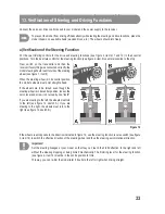
When the steering wheel is in its central position,
the model's wheels must point straight ahead.
If the wheels are to be turned even though the
steering wheel is in its central position, loosen the
servo lever and screw it on turned by one "tooth".
If you are steering to the left, the wheels must turn
to the left (see figure 12, sketch A). If you are
steering to the right, the wheels must turn to the
right (see figure 12, sketch B).
If the wheels react opposite to the direction indicated in figure 12, use the steering function reverse switch (see figure
2, item 14) to switch the effective direction of the steering wheel and thus the steering servo rotational direction.
Important!
Set the steering linkages at your model so that they can reach their full deflection to the right and left
without the steering stopping or being limited mechanically. The trimming lever for the steering function
(see figure 2, item 12) must be in the centre position for this.
This way, you can re-trim the model later if it pulls to the left or right when driving straight.
Figure 12


